Supernatural EMF Reader
This is a summary post of my finished “revision 1” EMF Reader from Supernatural. For revisions 2 and 3, please email me for the latest instructions.
Below you will find the following sections:
- Description and Pictures
- Part List
- Rough Step by Step Build Instructions
Hello Future Reader!
This guide is outdated as of 2018. If you purchased a kit from me, you have the 0718 revision. Watch this youtube build video instead of following the guide on this page.
https://www.youtube.com/watch?v=ce4PJZl9T2Y&t=1s&ab_channel=DustinWestaby
Kits for sale! https://westabyelectronics.com/store/shop/
Description and Background:
The EMF Reader in Supernatural is an excellent project for people like me that have some electrical knowledge. What I did was design a prop EMF reader around the Arduino platform so that it is actually functional while still looking like the prop from Supernatural.
I went to my local hardware store and bought an analog multimeter. After taking it apart, I played with it on an Arduino board and figured that it was possible to make a functional EMF reader using some off the shelf parts. I could even have the circuit play the telltale “erREEEEErr” sound on a speaker.
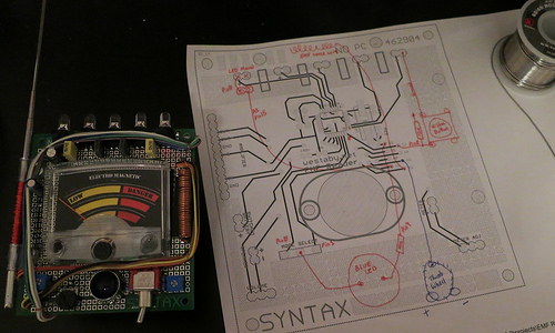
I finished the prototype circuit and proceeded to sourcing all the parts and designing a printed circuit board (PCB) that would do everything I wanted.
I measured the analog meter part with my caliper to ensure a good fit with the custom PCB.
In addition, this thread was very useful for finding reference pictures: http://www.therpf.com/showthread.php?t=115093
Functionality:
- Meter with a pin that bounces to high when triggered
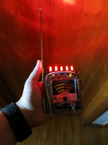
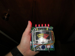
- Five top LEDs that match meter display
- Speaker that makes tone sweep sounds
- Hidden trigger button to override EMF “readings”
- Mode selector switch
- When not activated, the lights will blink every few seconds to indicate the meter is on.
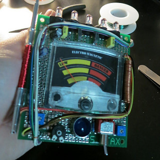
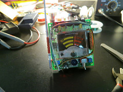
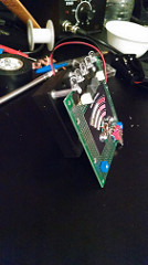
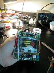
Pictures of my Completed Supernatural EMF Reader:
Step by step build instructions
The part list was moved to google drive so I can easily maintain it as links change. If you have trouble finding anything, do email me. I can help you track down the hard to find parts. thatdecade@gmail.com
https://drive.google.com/drive/folders/0B0uZYP7AohyhMHhjVFBlZ0F2ZVk?resourcekey=0-Dtz2g_vjZ7N3NBrnY1d7NQ&usp=sharing
Once you have gathered all the parts, it is time to assemble. This does require minor solder skills.
If you have never soldered before, it’s easy! Get a $5 solder iron from the hardware store and the thinnest solder spool you can find. Then watch some YouTube videos to see how it’s done. Through hole soldering of big solder points (like in this project) is great for learning.
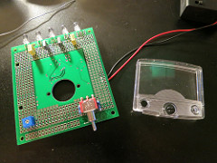
Salvage Parts and Test the Fit
Analog Meter
Take apart the multimeter to get at the analog mechanism inside. You will need the clear plastic from the front, the needle rotor, and the thumbwheel.
Cut a hole in the prototype board and do a “test fit” of the rotor. Make sure that it can spin freely. Eventually, it will be bolted down with washers to ensure the needle has enough clearance to move above the surface.
Switches and Knobs
Put all the various parts where you think they should go. Make sure that you have enough room for everything where you want them before you start soldering parts into place.
Assemble the functioning portion of the circuit
Arduino
You have two choices to get the circuit functioning. Use an Arduino Pro Mini or use an Atmega328p chip. The Arduino is easier and recommended. I chose the Atmega328p chip because I was using a custom made prototype board that had wires pre-routed to the various switches.
- Advantages of the Arduino Pro Mini: Easy to use and program over USB using the Arduino software. Use this for your source code: https://codebender.cc/sketch:56076
Note: there are 4 files to download. - If you choose the Atmega328p Chip, things get a little more complicated (you are on your own). More info here: http://arduino.cc/en/Main/Standalone
- If you purchased a circuit board from Dustin (me), then there is nothing you need to do. Your circuit is preprogrammed.
Mode Select Switch
Solder in place the toggle switch. Depending on your Arduino, pull up resistors may be required. More info here: https://learn.sparkfun.com/tutorials/pull-up-resistors/what-is-a-pull-up-resistor
Wire one of the toggle switch’s two side pins to pin 2 on the Arduino. The center is the common pin, wire to ground on the Arduino.
LEDs
Install the 5 LEDs at the top of the prototype board. The short lead from the LED goes to ground. The long lead from the LED goes to the Arduino.
Wire the LEDs to the Arduino pins in the following order: 2,4,6,7,8 (pin 5 is reserved for the meter output)
You can also install the white and yellow dummy square capacitors now if you like. These are cosmetic only and are not wired to the circuit. Solder them to the prototype board normally.
Cover the LED leads with electrical tape. This too is cosmetic, but also helps hold the LEDs down when you are handling the EMF reader.
Meter Potentiometer
Solder in place a blue square potentiometer. This will be used to adjust the meter sensitivity.
Pictured is my custom PCB. If you are using a different prototype PCB board, yours will look different.
Analog Meter
Install the meter onto the PCB, use two washers between the meter and the PCB to give the needle more clearance over the surface. Attach the meter using 2 screws, 8 washers, and 2 hex standoffs.
The washers on the backside of the PCB will help spread out the squeeze from the screw and hex standoff.
Wire the red wire from the meter to the analog output pin 5 of the Arduino through a potentiometer. The black wire goes to ground.
The potentiometer is used to “tune” the max point of the meter. The analog meter has a screw in the center; this is used to set the min point of the meter.
Later, when you are ready to power up, you can adjust the potentiometer with a screw driver until it performs right.
Printed Graphic
Download the .psd file here: https://www.mediafire.com/?cm0quv5bc5d9qa2
Print onto peel and stick adhesive photo paper, then trim the print then stick on the protoboard behind the meter’s needle.
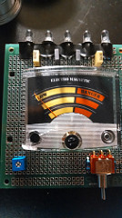
Use hot glue or epoxy to affix the clear plastic cover over the meter.
Assemble the cosmetic portion of the circuit
Capacitors
There are two round capacitors in the upper left corner of the board. Solder them in place. It is ok if they are not straight up and down.
Thumbwheel
Solder on the thumbwheel below the meter.
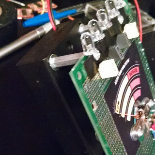
Antenna P-Clips
Place the antenna clips on the antenna and drill the prototype board so you can eventually bolt the antenna in place. Do not bolt down yet. Right now we just need to get the spacing between the P-clips in the correct position.
Coil 1
The first coil goes on the right hand side of the meter. Use your magnet wire to create this coil by winding the 22 gauge bare copper wire around a pen or screwdriver. Once the coil is long enough, cut off the excess and solder down.
With the coil soldered down, re-insert your pen or screwdriver and straighten the coil out.
Coil 2 (antenna)
The second coil is wrapped around the antenna between the two Pclips. Use the red magnet wire. This wire is a lot thinner and will take many layers. Just keep wrapping around until your coil looks right.
Antenna Bolts
It is now time to bolt the antenna in place. Use the screws, washers, and nuts.
Rainbow Wire
Take approximately 10 inches of rainbow ribbon wire and split them apart into separate strands. Half of the strands will run from the top right to the lower left. The second half of the strands will run from the lower right to the lower left.
Use more of the 22 gauge bare copper wire to create U shaped cable ties. Thread the ribbon wire under the U, then press down with a plyers and solder the U wire down.
If you look closely in the pictures, you can see these cable ties are used in the corners to hold down the ribbon cable.
Final Hex Standoffs and Battery Holder
Place the last two hex standoffs between the LEDs. With all four hex standoffs now attached, use them as a guide to cut holes into the battery holder and affix the battery holder to the EMF reader with more screws and washers.

Sound and Speaker
Pin 11 from the Arduino outputs the sound. However, if you connect a speaker directly to pin 11 and ground, you will have little volume. You need a speaker amplifier.
The PAM8403 is a cheap (under $2) small amplifier board. Wire the amplifier board to the battery power input, 4.5 volts. Then wire pin 11 from the Arduino into the input of the amplifier board. Lastly, wire the two wires from the speaker into the amplifier board’s output.