Updated EMF Reader – Assembly Guide

In 2015, I did a run of EMF readers with an updated design using an upgraded sound effects circuit. This is an assembly guide for making that EMF reader. For my older EMF Reader design that is not dependent on custom parts, see here.
There are two custom parts that you can purchase from me: thatdecade@gmail.com on etsy
Hello Future Reader!
This guide is somewhat outdated as of 2018 and is reference only. If you purchased a kit from me recently, you have the 0718 revision. Watch this youtube build video instead of following the guide on this page.
https://www.youtube.com/watch?v=ce4PJZl9T2Y&t=1s&ab_channel=DustinWestaby
Part List
The part list was moved to google drive so I can easily maintain it as links change. If you have trouble finding anything, do email me. I can help you track down the hard to find parts. thatdecade@gmail.com
https://drive.google.com/drive/folders/0B0uZYP7AohyhMHhjVFBlZ0F2ZVk?resourcekey=0-Dtz2g_vjZ7N3NBrnY1d7NQ&usp=sharing
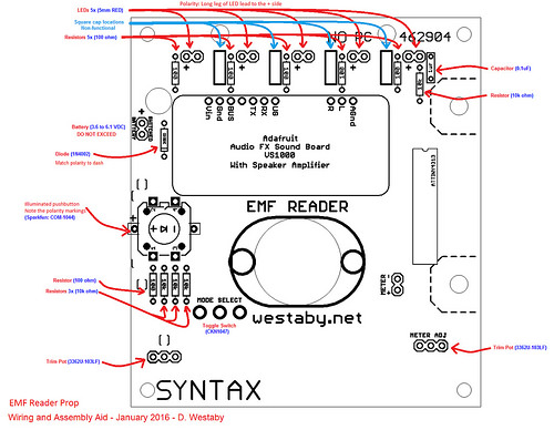
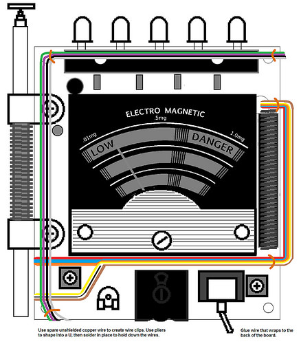
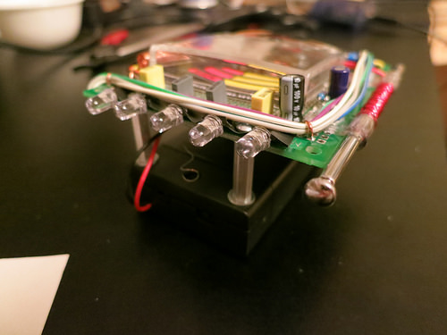
Solder the Back Circuit
Tools Needed: Solder Iron, Solder, and a Wire Cutter.
Parts Needed: Circuit Board, Preprogrammed Chip, 5x LEDs, 6x Resistors 100 ohm, 4x Resistors 10k ohm, Capacitor 0.1uF, Button, Diode, Audio FX Circuit, Speaker.
Instructions: Assemble as shown in the picture. The Audio FX Circuit needs 6 wires connected. Vin, Gnd, Bus, TX, RX, UB.
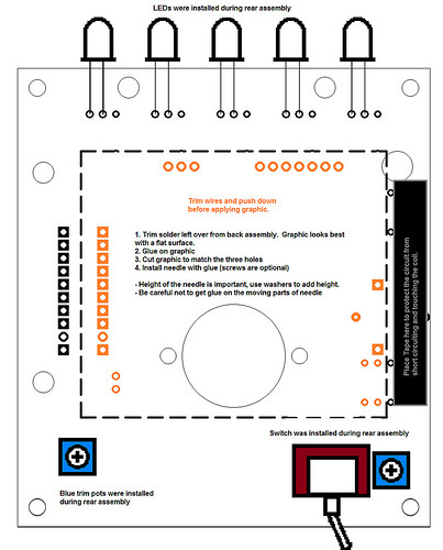
Trim, Tape, and Needle
Tools Needed: Electrical Tape, Scissors, Glue, Solder Iron, Solder, and a Wire Cutter.
Parts Needed: Needle Graphic, Meter Parts, 6x Washers
Instructions: Take apart the meter and remove the plastic wheel. You can now de-solder the potentiometer from the meter’s circuit board. Set aside. Next, cut the wires to the meter’s needle assembly leaving enough length to re-attach to the emf circuit. The needle assembly is screwed down and beneath the clear plastic housing that is also screwed down. Remove both. Be VERY careful with the needle assembly, it is fragile. Re-use the two screws from the needle to help align with the emf reader holes. You can use 6x washers to add some spacing between the needle assembly and the circuit board. This helps provide clearance and allows free movement of the needle. But be careful, as the washers are magnetic.
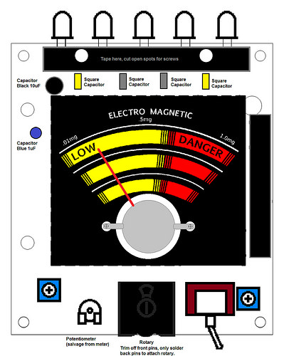
Solder the Front Circuit
Tools Needed: Screwdriver, Electrical Tape, Solder Iron, Solder, and a Wire Cutter.
Parts Used: 2x Yellow Square Capacitors, 2x Gray Square Capacitors, Toggle Switch, 2x Trim Pot, Rotary, Capacitor Blue 1uF, Capacitor Black 10uF, Potentiometer (salvaged from meter circuit).
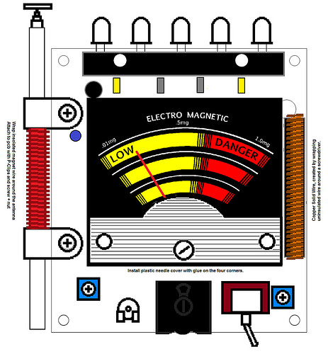
Meter and Coils
Tools Needed: Screwdriver, Solder Iron, Solder, and a Wire Cutter.
Parts Needed: Antenna, Magnet Wire, P-Clips, Solid Core Wire (strip off the rubber sheath)
Wire Clips
Tools Needed: Pliers, Solder Iron, Solder, and a Wire Cutter.
Parts Needed: Rainbow Wire, Solid Core Wire (strip off the rubber sheath)
Battery Box
Tools Needed: Pencil, Drill, 1/8″ Drill Bit, Screwdriver
Parts Needed: 2x Screw Posts, 4x Screws, 6x Washers, Battery Clip.
Instructions: Make room in the battery box for the screws in the battery box by removing a bit of plastic from behind the switch. No cutting needed, the plastic pops out. Align the battery box cover with the circuit board. Make two marks in the cover with your pencil. Make 1/8 inch holes with the drill in the marked spot. Use the washers as follows: SCREW |== (WASHER) |PCB| (WASHER) ==POST== (WASHER) |COVER| ==| SCREW
Assembly is now complete, calibrate and learn how to use your emf reader below.
Load the Sound Clips
Adding new sound effects to the EMF Reader is simple. Just plug into the usb port to a pc. The EMF Reader will mount as flash storage on the pc. Drag and drop the new .wav or .ogg file, then “eject” to safely remove the usb device.
Audio Files:
Guides:
https://learn.adafruit.com/adafruit-audio-fx-sound-board/copying-audio-files
https://learn.adafruit.com/adafruit-audio-fx-sound-board/creating-audio-files
Next step is selecting the new sound on the EMF Reader. The EMF Reader reads the first 5 files in storage and maps them.
To select the new sound, turn on the EMF Reader then move the mode select toggle switch to the center position. There is no center position, so you will have to balance it there. When you have correctly set the center position, the light on the back of the reader will rapidly flash.
With the EMF Reader in setup mode; press the button on the back to cycle through any of the first 5 files. When the correct file plays, flip the toggle switch to exit setup mode.
EMF Reader Outline
Get to know your EMF reader. Note the numbered arrows in the picture.
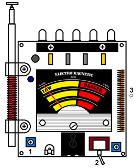
- Needle Calibration Screw Wheel, Sets high position
- Toggle Switch: Mode selection.
- Hidden Button: Located on the back of the EMF Reader, use this button to override normal EMF operation and force a “ghost” event.
Meter Calibration
Left blue screw wheel calibrates the analog meter needle high position. Place the EMF Reader in interactive mode, and hold the hidden button. This will hold the meter needle high. While holding the button, use a screwdriver to adjust the needle’s high position.
Modes of Operation
| How to Enter | Primary Modes | Alternate Modes |
|---|---|---|
| Prop Modes Change toggle switch to the right position. | Pressing the hidden button will activate the sound and light pattern. | Sound and light pattern will run in a loop, cycling between high and low readings. |
| Interactive Modes Change the toggle switch to the left position. | Press the hidden button to activate the meter. Meter and lights stay high until the button is released. | EMF Reader will always read as high until the hidden button is pressed. |
*Hold the hidden button while power cycling to enter an alternate mode.
**In modes that do nothing until the button is pressed, lights will blink every few seconds to indicate the meter is on.
Troubleshooting
Meter does not sweep or sweeps too high
- Needle is touching the back. Use a tweezers to push away, bending slightly out.
- Meter potentiometer needs calibration. See Meter Calibration above.
- Debris has gotten stuck in the meter’s electromagnet. Gently spin the magnet and ensure that it doesn’t “catch” anywhere. Even something as small as a hair can prevent free spinning.
Sound is garbled and sounds bad
- Voltage to the speaker amp is too low. Replace the batteries.
- Not all sound files sound great on the small speaker, experiment with other sounds.
Note: Be sure to use good batteries. Recommend: Energizer Ultimate Lithium.