Menu
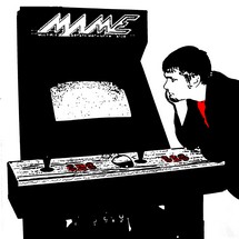
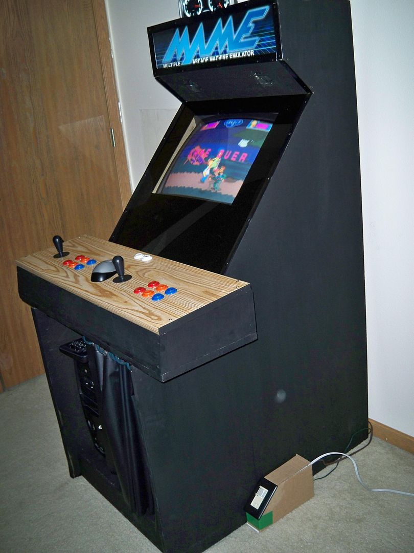
Arcade Renovations
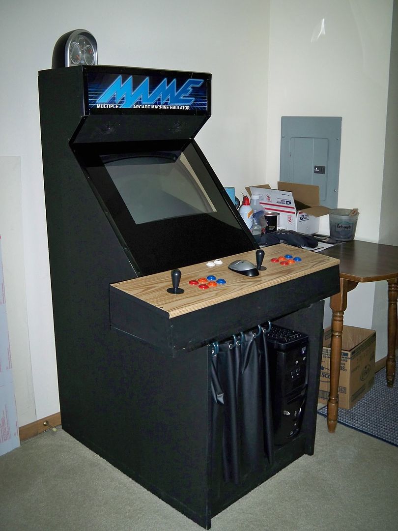
The original scope of the renovations was adding plexiglass as a bezil and using the left over material as a new protector for the marquee. Of course after "popping the hood" I noticed many other things to improve upon or were left unfinished.
See design notes from the original design five years ago on
this page.
More pictures of the renovation are available here:
Arcade 2008 [photobucket.com]
Bezel & Marquee
I've worked with plexi before and it's no picnic because it is very fragile and difficult to cut. I made the decision to upgrade to Lexan. All the advantages of plexi and near indestructible too. Lexan blows plexi out of the water as a working material.
Downside is Lexan is an expensive material. Lexan is near double the cost of plexi. 36"x24" was the largest available and anything smaller wouldn't have covered the 24"x24" bezel opening. That's the price of a material that can survive being hit by a hammer.
Since I had already replaced the old monitor with a medium size
 tv it stuck out past where the bezel was to be inserted about a
1/4". This turned out to work to my advantage and gave a slight
bulge to the Lexan. This pushed it firm against the molding
around the sides of the cabinet.
tv it stuck out past where the bezel was to be inserted about a
1/4". This turned out to work to my advantage and gave a slight
bulge to the Lexan. This pushed it firm against the molding
around the sides of the cabinet.
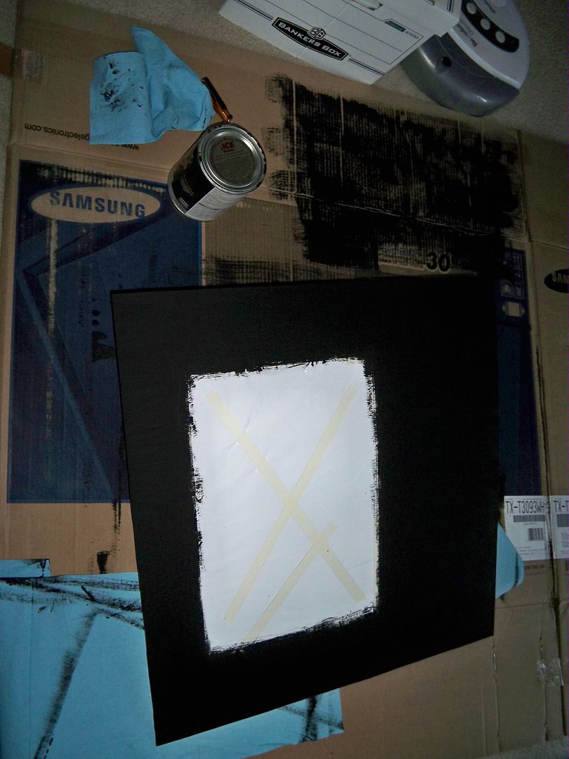
With the Lexan in place I was able to tape off the visible section for painting. It took several coats for it to be solid but the back of the Lexan was painted with a oil based black paint to match the rest of the cabinet.
 I did end up having plenty of lexan left over. Enough to cover
the marquees three times. I needed two of the pieces, one for
each side of the photo paper. The paper was re-used from the
original design so it has been through a lot showing bends and
small creases. Putting the Lexan on either side of it flattened
it back out and made it look proper again. If you look close
you can still see the wrinkles, but that is no big deal.
I did end up having plenty of lexan left over. Enough to cover
the marquees three times. I needed two of the pieces, one for
each side of the photo paper. The paper was re-used from the
original design so it has been through a lot showing bends and
small creases. Putting the Lexan on either side of it flattened
it back out and made it look proper again. If you look close
you can still see the wrinkles, but that is no big deal.
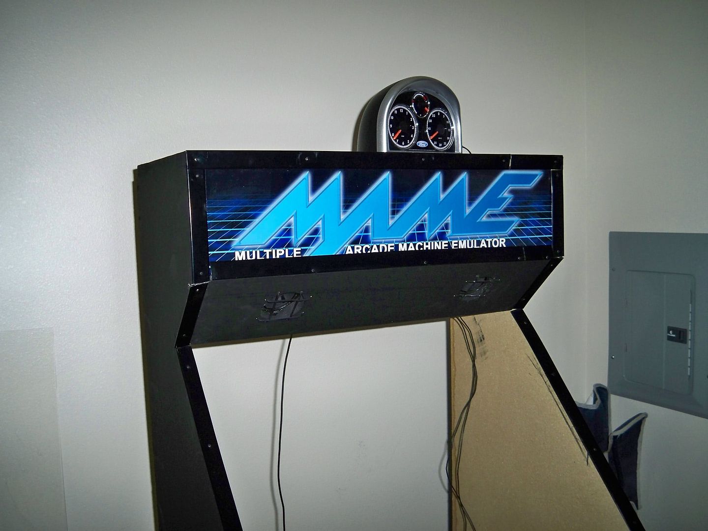
Now it needed proper lighting. A fluorescent backlight was used to illuminate the marquee before, but lexan is a natural blocker of UV light, so it had to go. It was never proper anyway and always under lighted the marquee. The solution was a CCFL (Cold Cathode Fluorescent Light) bar. They are cheap (under $15 for the largest size, 15") and run on 12V. These things are staples in PC modding and lighting. Problem was that it needed 12Vdc from a PC. I didn't want it running all the time or even when the pc was in sleep mode so the CCFL needed a second power supply. I had a closest full of them, so it wasn't a problem.
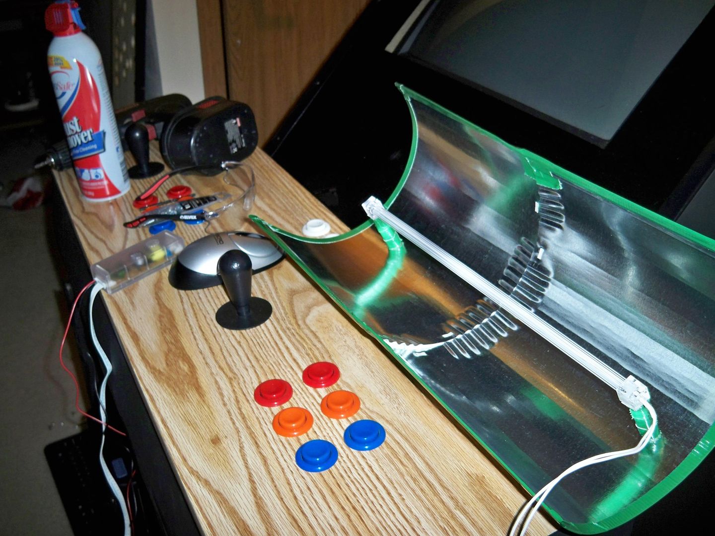 Another consideration that was needed was the CCFL needed a
reflector. The light bar was 15" but the marquee opening to
light was 24". A reflector and proper spacing would provide the
needed coverage. I found some dryer vent halves and strung two
together with the temporary solution of duct tape, then drilled
Another consideration that was needed was the CCFL needed a
reflector. The light bar was 15" but the marquee opening to
light was 24". A reflector and proper spacing would provide the
needed coverage. I found some dryer vent halves and strung two
together with the temporary solution of duct tape, then drilled
 a few holes and made some standoffs for the CCFL bar to sit on
to get it at the proper distance from the reflector and maximize
the light. Screwing it to the cabinet holds the duct tape tight
and makes it a permanent fixture.
a few holes and made some standoffs for the CCFL bar to sit on
to get it at the proper distance from the reflector and maximize
the light. Screwing it to the cabinet holds the duct tape tight
and makes it a permanent fixture.
Lastly, to finish the lighting was to cover sections of the
cabinet where I didn't want light leaking. The light bar floods
the internal cabinet with light and it comes out in strange
 places. Like the tv bezel and cracks between the speaker holes
and the speakers. This was solved with a staple gun and the
cheapest black fabric I could find. $1 per yard is hard to beat
and I only needed one layer to block the light from invading the
bezel and elsewhere.
places. Like the tv bezel and cracks between the speaker holes
and the speakers. This was solved with a staple gun and the
cheapest black fabric I could find. $1 per yard is hard to beat
and I only needed one layer to block the light from invading the
bezel and elsewhere.
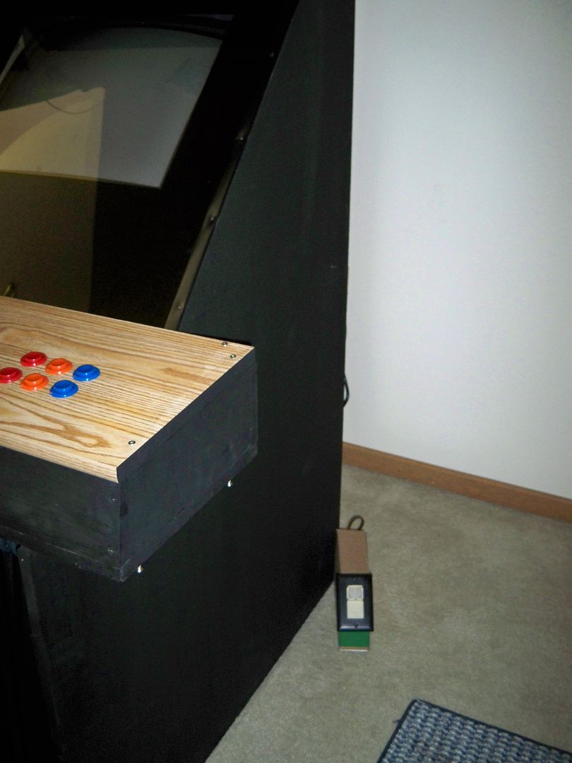
Control Panel
The old control panel was a pre-sanded piece of countertop.
After painting this looked pretty good. Fast forward a few
years and it is certain that it wasn't protected enough because
 it showed many minor scrapes and several deep scratches.
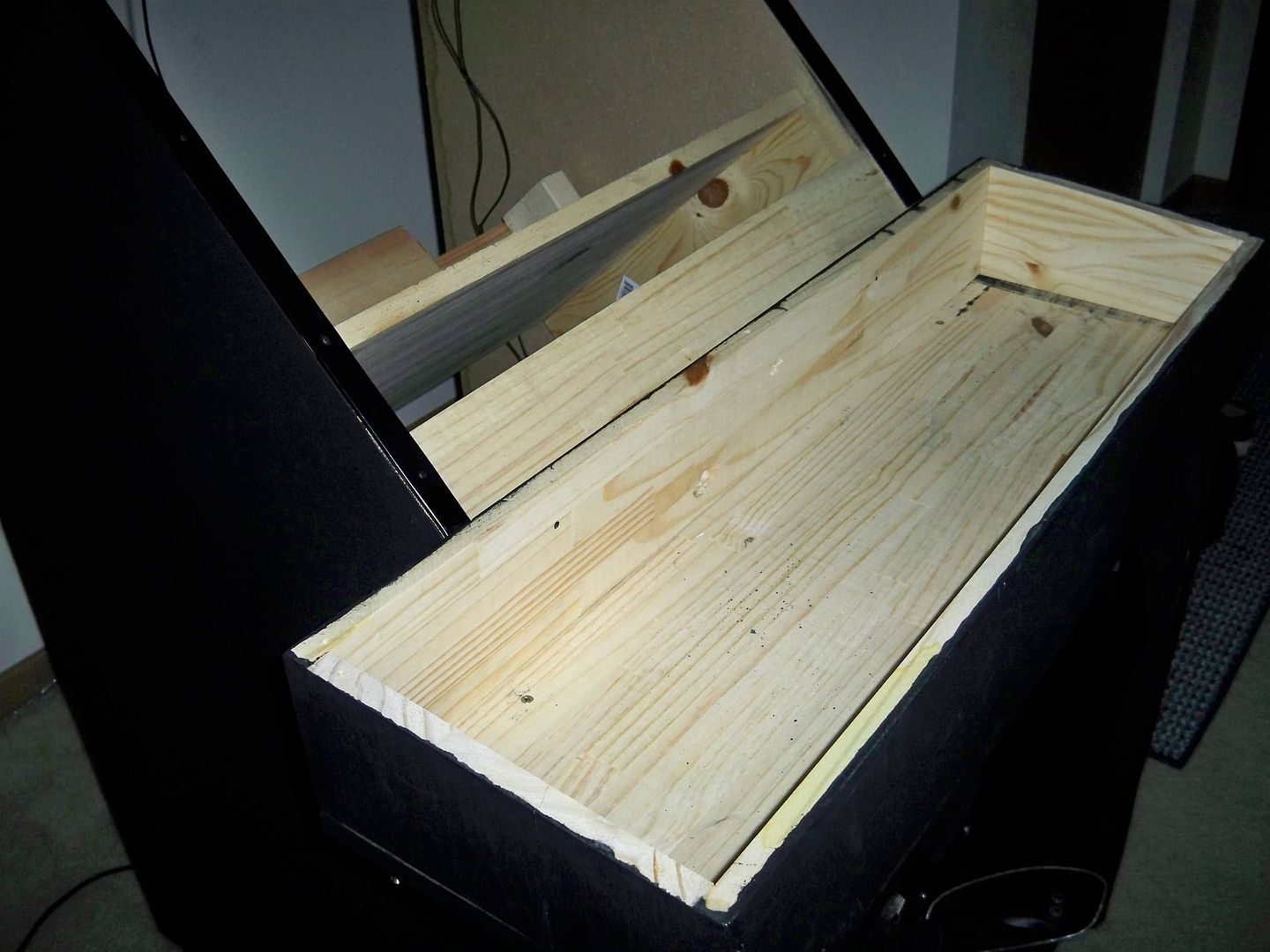
The new control panel will follow the same style. A countertop
or shelf board that is prefinished for the best appearance. The
difference is that the new board will also come with veneer
applied to the top, bottom, and front side. I decided not to
paint this to give the cabinet a two tone look. Everything
 being black was a bit much anyway and the simulated stained
surface looks great. The new board is even a bit thinner than
the old board allowing me to tighten the pushbuttons better (the
old board was almost too thick).
being black was a bit much anyway and the simulated stained
surface looks great. The new board is even a bit thinner than
the old board allowing me to tighten the pushbuttons better (the
old board was almost too thick).
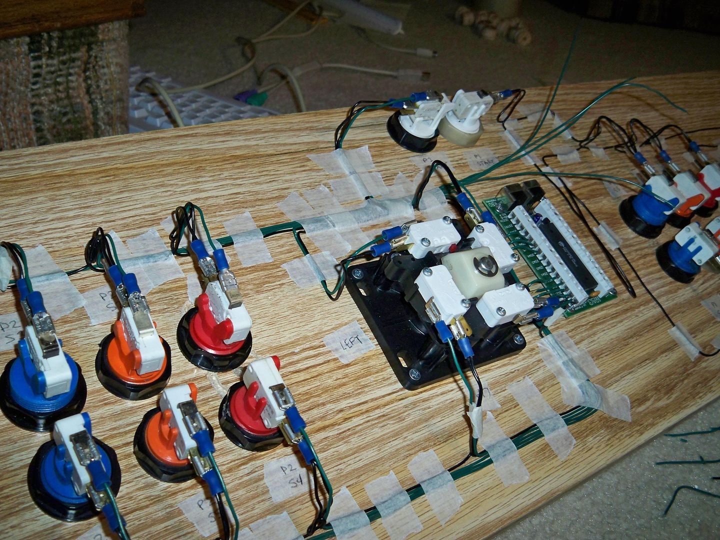
This also gave me the chance to change the design of the original control panel, which was diamond based, and allowed me to move to a more traditional fighter layout. Moving the coin inserts to the sides and moving the player one and two start buttons to the top row. Not only does this keep the coin inserts out of the way it also presents the future opportunity to play virtual pinball type games.
The old player one and two start buttons were (like all my original pushbuttons) bought used from the local vending company. So there were already a few scrapes on the buttons. Which was fine for everything except the player one button. This button is pressed very often and did show a lot of wear. More specific, only the feet of the little person drawn was still there. I got around this with magic marker but that was a short term fix. After a week or two it would wear off again. A more permanent solution was to replace the button. I figured since I'm ordering why not replace the player two pushbutton too and get some nice black pushbuttons for the side coin inserts to match the paint job.
Cheapest place to find pushbuttons in small quantities, believe it or not, is ebay. A quick message to the seller asking about the hole width and depth and we are in business. I use 1" holes and the pushbutton must be capable of fitting a depth of over 1".
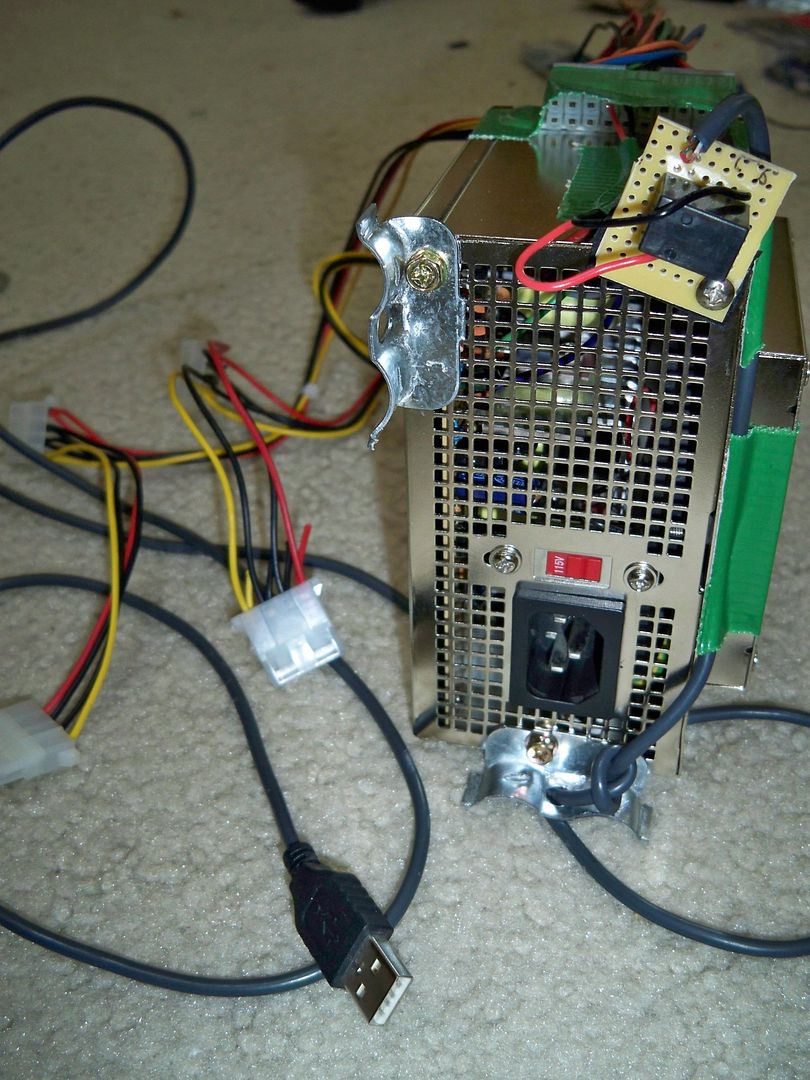
Power
A simple spike strip or UPS and we're done right?
right?!
Nope, can't make anything easy on myself. The original cabinet had no power control. All devices needed to be turned on and off one by one. This time around I wanted everything to turn off and on together and the tv to not come on until the computer has finished booting.
Easiest way to accomplish this is with what they call a 'smart strip'. It is a power strip that will monitor the current running to the PC. If the PC turns off or hibernates the 'smart strip' will power off all other devices connected to it. Retails for about $40.
That is fine and great for some people, but it is tricky to adjust the current sensor for on vs standby. A 'smart strip' also will not keep the monitor turned off until the pc finishes booting.
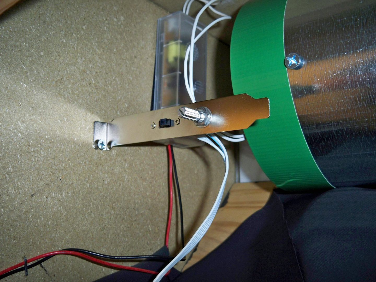
My solution? Give control to the pc. Being a programmer myself, writing a program that will trigger on the computer's screensaver and output high or low voltage to the parallel (printer) port and control the cabinets power through a few relays is a simple task. Interesting enough, someone beat me to the idea and already wrote an application. Even took some pictures and made this excellent guide.
Peripheral Power control with screen saver [Instructables.com]
That guide was good for starters, but it doesn't provide very much protection to the pc and cannot be used with a single mechanical high amperage relay.
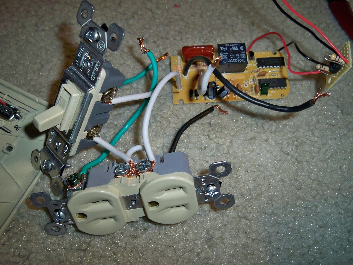 I already had a 6A 12V relay from a failed remote christmas
light on/off retail product. So why spend the money on solid state
relays that can only provide enough current for one device at a
time when I have this great relay that can provide current to
all my devices?
I already had a 6A 12V relay from a failed remote christmas
light on/off retail product. So why spend the money on solid state
relays that can only provide enough current for one device at a
time when I have this great relay that can provide current to
all my devices?
Protecting the computer from any over current or back voltage
situations was easy enough. I had a spare optical isolator
IC in my part bin (LED and photo-transistor package). The
computer can supply enough current to power a LED, but if you
 tried taking much more current you would blow your motherboard).
I connected the transistor like a switch for the relay circuit.
tried taking much more current you would blow your motherboard).
I connected the transistor like a switch for the relay circuit.
Real problem was I had to re-wire the relay circuit for a hold on, release off. The original setup was for a microswitch pulse input and click on, click off. Pretty simple stuff. Followed the traces to find where the relay is powered from. In this case it was a power transistor. The transistor was triggered by IC logic. Perfect. great. That will do. Toss the IC logic and wire in my own transistor to send voltage to the power transistor to power up the relay.
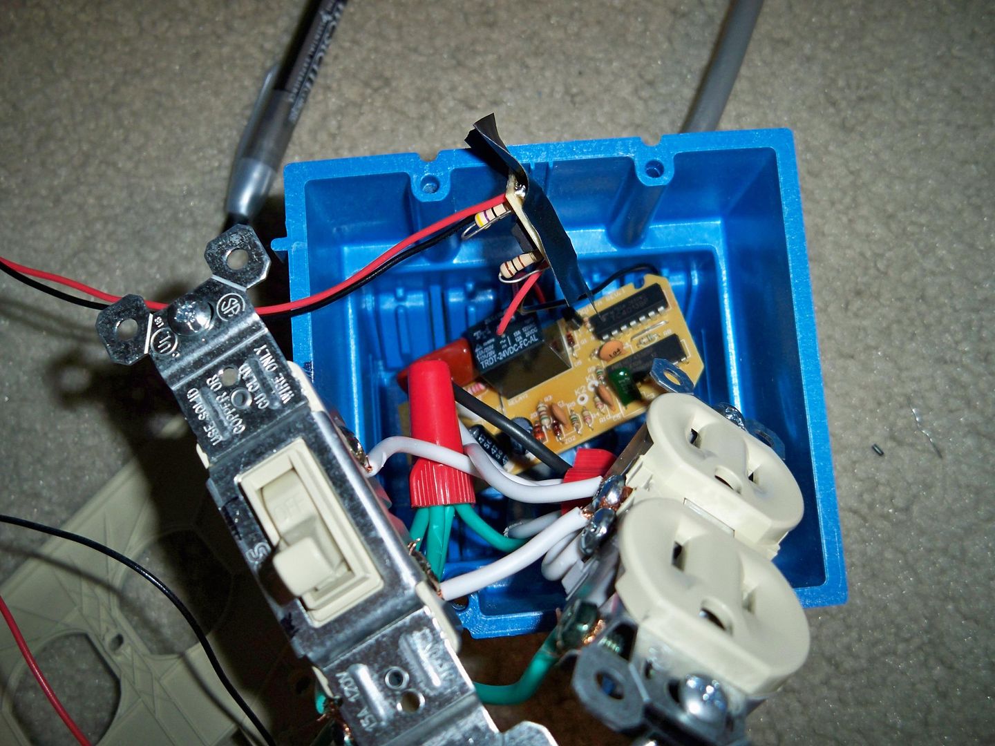
Got myself a double gang receptacle box that was extra deep. Outlet on one side an override switch on the other side. The override switch is a normal house wiring switch wired in parallel with the pc control. So the outlet can be turned on when the PC is off or not connected (great for repairs / debugging).
The box has plenty of room for the circuit boards in the back of the box with all the AC connections.
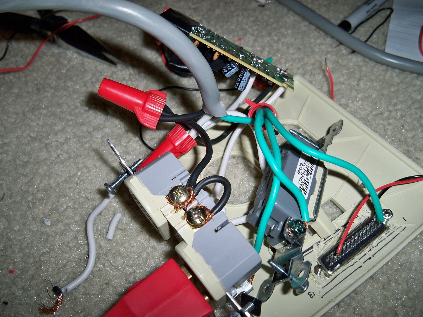
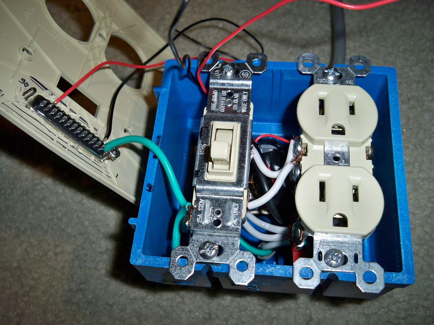 Did I mention the DB25 connector on the front of the box? Used a
sanding tool to make a hole to mount a female parallel port to
the front. That way I don't have to cut a printer cable and the
cable can be disconnected when needed.
Did I mention the DB25 connector on the front of the box? Used a
sanding tool to make a hole to mount a female parallel port to
the front. That way I don't have to cut a printer cable and the
cable can be disconnected when needed.
In retrospect I should
have put some standoff nuts on there. That way the cable could
be fastened down. Not like anything would tear it off the
connection, but it would have been nice to secure it.
For the extra mile I also added a motion sensor. The same kind
that you would use for an outdoor flood lamp but a smaller indoor
version. Because of the design of the motion sensor it was
 connected like a switch on the hot wire only, instead of both the
hot and the ground wire. This means the motion sensor had to be
connected to a device that would draw enough current when
powered off so the motion sensor could be passively powered.
Connecting it to a transformer/relay was not enough current so I
connected a small 10" fan in parallel (smallest AC fan I
could find).
connected like a switch on the hot wire only, instead of both the
hot and the ground wire. This means the motion sensor had to be
connected to a device that would draw enough current when
powered off so the motion sensor could be passively powered.
Connecting it to a transformer/relay was not enough current so I
connected a small 10" fan in parallel (smallest AC fan I
could find).
The transformer I connected to the motion sensor steps down the voltage to 5Vdc which runs to a relay. The relay connects to the ipac keyboard encoder. Somebody walks up, a key is pressed, system 'wakes' up from screensaver.
The motion sensor is not sensitive enough to detect a person standing in front of it constantly. It will only trigger on heat sources moving in and out of it's field of vision. This worked to my advantage because continually holding down a key on a keyboard causes the ipac's shift functions to stop working (holding 1 player start & 2 player start = esc stops working). I also set the motion sensor's timer to the lowest setting (~10 seconds), so if there is a problem it will only exist in this timeframe.
 The last step was to have it control the CCFL lamp for the marquee.
The motion sensor could not be powered on the same circuit as a
fluorescent light. The starter puts spikes on the line that
interfere. So I couldn't directly power it with the relay I
had just prepared. So I gave the PC control over the power pins
of the power supply instead. To turn on a PC power supply 2 pins
need to be connected on the motherboard connector. One is +5V,
the other is the power control (any red wire and the only green wire).
I plugged a transformer to the control box I already built. Stepped
down to 5 Volts so it was switching on and off a second relay
in series. That second relay simply connected those two wires on
the power supply.
The last step was to have it control the CCFL lamp for the marquee.
The motion sensor could not be powered on the same circuit as a
fluorescent light. The starter puts spikes on the line that
interfere. So I couldn't directly power it with the relay I
had just prepared. So I gave the PC control over the power pins
of the power supply instead. To turn on a PC power supply 2 pins
need to be connected on the motherboard connector. One is +5V,
the other is the power control (any red wire and the only green wire).
I plugged a transformer to the control box I already built. Stepped
down to 5 Volts so it was switching on and off a second relay
in series. That second relay simply connected those two wires on
the power supply.
![]() Connected the power supply to an isolated UPS source and everything
was fine. That same UPS protects my pc from power loss / damage. So
now when power is lost both the PC and the light bar will be
protected.
Connected the power supply to an isolated UPS source and everything
was fine. That same UPS protects my pc from power loss / damage. So
now when power is lost both the PC and the light bar will be
protected.
The new power systems worked together better than I expected. Turn on the pc and everything remains off until windows has loaded and runs the autostart LPT control program. Everything lights up and the speakers turn on just in time for the windows startup sound. Have all power saving settings disabled and the screensaver is set for ten minutes. Walk away for ten minutes and everything goes dark. Walk back up and everything lights back up.
The motion sensor only catches you about 60-70% of the time. If it doesn't, just wiggle a joystick or hit a button and the system will light up again. I measured about a 2 second lag for the tv to power up. The speakers and lamps are near instant.
Software
 Work in progress. Have a working and configured old version of
MAMEWAH. Want to update to the latest version which means that
butler configuration helper program will no longer work.
Work in progress. Have a working and configured old version of
MAMEWAH. Want to update to the latest version which means that
butler configuration helper program will no longer work.
Currently there is no frontend software running. Just links on the desktop to run a few choice games.