Ammo Counter Assembly Instructions
DIY assembly guide for the ammo counter. If you ordered an unassembled circuit kit, this is the instruction page for you.
Assembly order is from the center outward to minimize solder bridges. Keep some solder removal braid handy to remove any bridges between pads.
BACK OF THE PCB
- Install the IC, making sure to orient with pin1 indication on the PCB
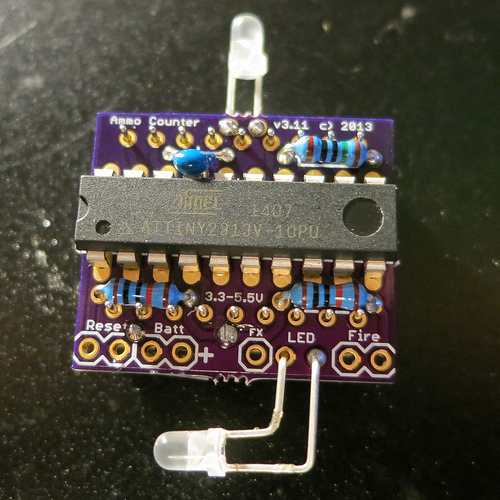
- Install the three resistors.
- 2x 10k on the bottom
- 100 ohm on the top
- Install the LEDs and bend into position to match your install location.
- LED on top center position (unmarked)
- LED on bottom marked position.
Note: The LED polarity is not marked on the board. See the wiring section for additional help.
You can also look at the copper traces that connect to the LED socket. The ground is connected in multiple points. The positive is connected to a single trace.
- Install the capacitor to the top of the PCB.
FRONT OF THE PCB
- Install the diode, leave the leads long and do not solder yet.
- Install the display but do not solder yet. Orient the same as the graphic 8.8.
- Bend the diode down and out of the way of the display.
- Solder the display and diode.
WIRING
+---------------------------+

|+-------------------------+|

||  +-----+      +-----+   ||

||  |     |      |     |   ||

||  |     |      |     |   ||

||  +-----+      +-----+   ||

||  |     |      |     |   ||

||  |     |      |     |   ||

||  +-----+ .    +-----+ . ||

|+-------------------------+|

|1 2   3 4   5  -====-  8 9 |

+---------------------------+
+---------------------------+

|           11 10           |

| .  .  .  .  .  .  .  .  . |

|    =.1uF=          =100=  |

|---------------------------|

|\   ATTINY2313            ||

|/                         ||

|---------------------------|

|  =10k=             =10k=  |

| .  .  .  .  .  .  .  .  . |

|9 8   7 6    5    4 3   2 1|

+---------------------------+
| Signal Name | Location | Ground |
|---|---|---|
| FIRE SWITCH | 1. Fire Signal | 2. Ground |
| AMMO AVAILABLE LED | 3. LED + | 4. Ground |
| POWER | 6. Battery + | 7. Ground |
| RELOAD SWITCH | 9. Reset Signal | 8. Ground |
| Top LED (Always ON) | 10. LED + | 11. Ground |
| Muzzle Flash | 5. FX |
Note: Power socket overlaps with the diode. Be careful not to short.
TESTING
- After connecting power, you should see the display light up with the current clip size.
- Press the fire button to decrement the ammo count.
- Press the reload button to reset the count.
- When the count reaches zero, the Ammo Available LED will turn off.
- Additional fire modes are accessed by holding the fire button while pressing reset. Display will read F1, F2, F3 to indicate the selected fire mode and clip size. Release the fire button to save your selection.
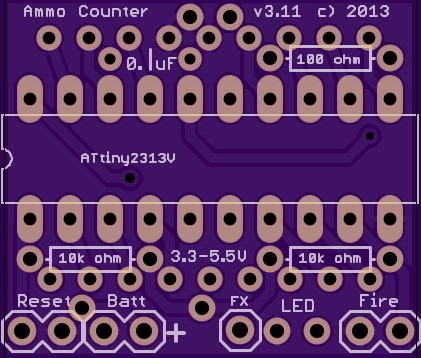
PCB Trace Reference
This section is useful for modification and troubleshooting. You can see where the trace wires go on the pcb.
Top
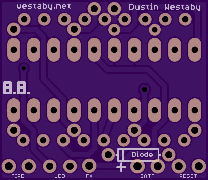
Bottom
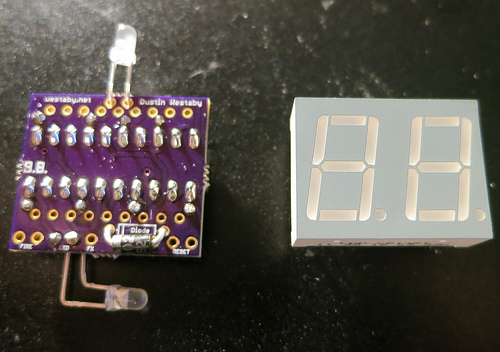
Reference Pictures
Additional pictures are on flickr.
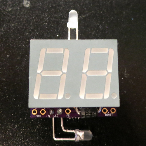
Final assembly. Shows placement of diode below the display.
Display is not soldered down yet. LED leads bent to match install positions. Shows orientation of chip.
Top resistor pictured is 150 ohm, kit includes 100 ohm.
Orientation of display to front