DIY Ammo Counter
Do you need an ammo counter circuit for your project and are bummed that you have to wait for a spot in my build queue to open up? Fret not, here is a step by step how to make one from scratch!
In this guide, I will detail how to build your own ammo counter for ~$25 and with only minimal soldering experience.
Parts:
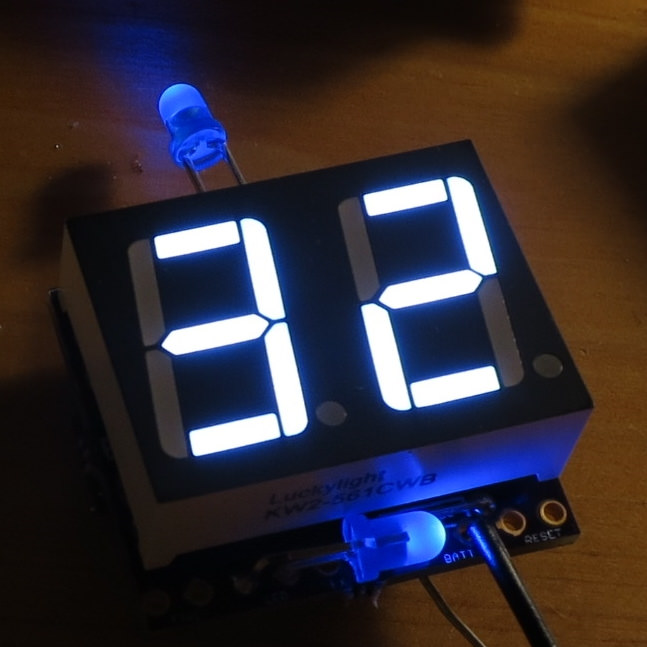
- Dual Digit Seven Segment 0.56inch ‘Common Cathode’ Display
- Adafruit Arduino Trinket
- Lever switches that fit in most projects
You can use other arduinos or switch and display choices. The linked ones were chosen for number of pins and size. This project uses 16 IO pins from the arduino and the trinket is the smallest arduino that can be programmed over usb.
If you get a different display, it must have the following traits:
- Common Cathode, the common pin is ground (do not want Common Anode)
- Two Single Digit 7 segment displays, with 10 pins on the back EACH.
– OR – - One Dual Digit 7 segment display that is non-multiplexed, with 18-20 pins on the back (multiplexed only has ~10 pins)
Wire Display to Arduino:
Get out your solder iron, wire strippers, and some note paper.
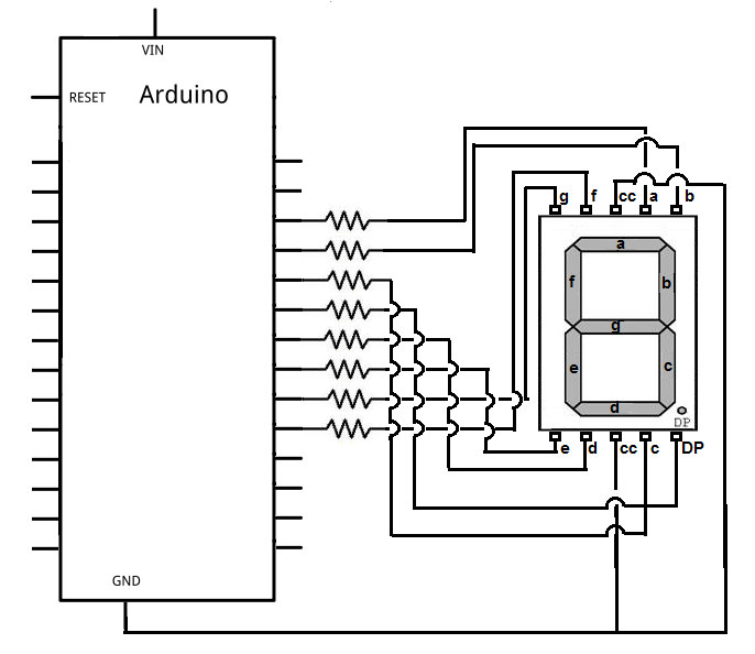
- Wire display digits 1 and 2 as shown below, diagram only shows one digit for simplicity.
- The common pin (CC) goes to ground.
- The period (DP) can be left unwired.
- Each segment is wired to a unique pin on the arduino, can use any arduino pin marked as D or A.
- The exact pins wired to are important, write them down for later. To run the software without modification, use the default pinout table below.
- Diagram shows resistors between the display and the arduino. When using the 3.3 volt version of the arduino trinket, no resistors are needed.
Default Arduino Pinout
| Arduino | Trinket | I/O | Signal Type | Name |
|---|---|---|---|---|
| 3 | ~3 | O | Display Output | Digit 1, Segment E |
| 4 | 4 | O | Display Output | Digit 1, Segment D |
| 5 | ~5 | O | Display Output | Digit 1, Segment C |
| 6 | ~6 | O | Display Output | Digit 2, Segment E |
| 8 | 8 | O | Display Output | Digit 2, Segment D |
| 9 | ~9 | O | Display Output | Digit 2, Segment C |
| 10 | ~10 | O | Display Output | Digit 2, Segment B |
| 11 | ~11 | O | Display Output | Digit 2, Segment A |
| 12 | 12 | I | Switch Input | Fire Switch |
| 13 | 13 | I | LED Output | LED |
| 14 | A0 | O | Display Output | Digit 2, Segment F |
| 15 | A1 | O | Display Output | Digit 2, Segment G |
| 16 | A2 | O | Display Output | Digit 1, Segment B |
| 17 | A3 | O | Display Output | Digit 1, Segment A |
| 18 | A4 | O | Display Output | Digit 1, Segment F |
| 19 | A5 | O | Display Output | Digit 1, Segment G |
| RST | RST | I | Switch Input | Reload Switch |
Finish Wiring Assembly:
- Wire the fire switch to a digital pin and ground.
- Wire the reload switch to the reset pin (RST) and ground
- Wire in the trinket to a 3.3 – 5 volt battery pack, blue and white color displays requires minimum of 3.2 volts.
Program Software:
You will need a micro usb cable. No batteries needed yet, the trinket is powered by the usb for now.
Source Code:
- Follow the getting started guide from codebender to setup the website to talk to your arduino trinket, choose Adafruit Pro Trinket 3V USB when asked
codebender.cc/static/walkthrough/page/1 - Open source code link
- Click Run on Arduino
- If you get the error message, make sure to press the button on the Trinket to activate the bootloader before trying again.
Optional Software Changes
With the source code open on the codebender.cc website, find and click the edit button to make changes to the software. After you have made changes, click Verify Code and resolve any issues, proceed to ‘Run on Arduino’ when the website indicates ‘Verification successful!’
- If you did not use the default pinout, you must update the pinMap list with where you wired each display segment. Use the pin numbers you wrote down
- If you want to use a different starting ammo count or firing types, scroll down and update ‘Starting Values’.
- shotmode can be set to CONT for full auto or BURST for semi auto
- burst_value is the number of ammo shot in each burst, default is 1.
- counter_value is the starting ammo value.
Examples:
- shotmode = BURST; burst_value = 1; counter_value = 99; is used for paintball or nerf
- shotmode = CONT; burst_value = 1; counter_value = 60; is used to match a Halo AR MA5B
- shotmode = BURST; burst_value = 3; counter_value = 36; is used to match a Halo BR55
Testing:
On startup, you will see the starting count of MODE1. Press the fire button and the number will go down 1 tick until 0. The LED (pin 13) goes dark when the counter reads 00.
Press the reload button and the display will go blank, and then reset to the starting count.
Hold the fire button down while pressing reset, this will change between modes. Display will report the mode number as F1, F2, F3, and so on.
Feel free to play with the software further to tweak the features to your liking. Have fun :)