NESPi NFC Electronics Kit Assembly Guide
This is a circuit assembly guide for the DaftMike DIY clone kit and is similar to his video guide. You will be wiring a NFC Reader into an Arduino that communicates with your Raspberry Pi to launch games.
This guide assumes that you already have an Assembled 3D Printed Mini NES Case, and have purchased or made an Electronics Kit circuit needing some soldering to assemble. The Electronics Kit can be purchased or built. Sellers and Schematics are available on the Facebook Mini NES Builders Group and on etsy.
For the next part of this guide, visit the Software Install page. If you have any questions, please post them to the Facebook Mini NES Builders Group.
If you find anything that needs to be updated, please contact Dustin Westaby on facebook.
Tip: You can find combo deals on Amazon for the Raspberry Pi, Heatsink, and Fan.
Part List
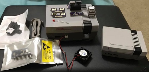
Before we start you will need to make sure you have:
- 3D Printed Mini NES Case
- Raspberry Pi 3 Model B Motherboard
- NES30 Wireless Bluetooth Controller or USB Classic NES Controller (optional)
- Heatsinks (optional)
- Arduino Pro Micro
- PN532 NFC reader
- NTAG216 NFC tags
- 25mm 5V Fan (optional)
- Electronics Kit
Updated: Aug 2017 - This electronics kit is currently available on etsy for a limited time! Click here.
Electronics Kit Contents:- Main PCB
- USB Extender PCB
- USB Socket PCB
- Front Panel PCB
-
Misc Parts:
- 7x7mm Latching Pushbutton Switch
- 7x7mm Momentary Pushbutton Switch
- Dual USB Socket
- 3mm Red LED
- 2x5 Female Pin Header
- 10 Wire Ribbon Cable
- Quick Connector Cable
- Glue Dots
You can follow this guide without the Mini NES Case. However, you should wait before trimming wire lengths until you have the case in hand to compare to.
Tools List
These tools are useful when following this guide. Approx prices are listed.
- Solder Iron ($30)
- 0.3mm Solder ($3)
- Flush Wire Cutters ($2)
- Wire Strippers ($5)
- Super Glue ($1)
Before you begin, watch this video on youtube to become a soldering pro!. Soldering is EASY. If that video is too long, you can learn from any of these videos in just a few mins.
Remove the SD Card
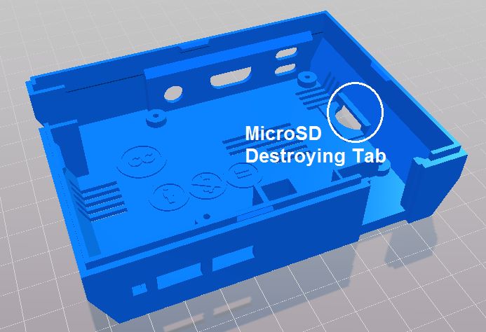
Damage Warning! If you have an SD Card installed in the Raspberry Pi, remove it now!
The 3D Printed Case has a defect that will snap in half the SD card when the Raspberry Pi is inserted OR removed from the Mini NES Case.
Front Panel Assembly
You will have two almost identical switches for the Front Panel PCB. Do NOT solder the switches onto the PCB yet! Click the switches up and down to figure out which is the Latching Pushbutton Switch and which is the Momentary Pushbutton Switch.
The Latching Pushbutton Switch is the POWER button.
The Momentary Pushbutton Switch is the RESET button.
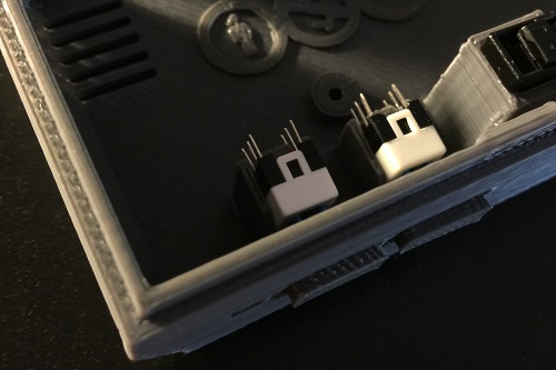
- Snap the button covers on to the Pushbutton Switches.
- Install the two switches into the 3D Printed Button Holder before sliding into the Front Panel PCB.
- Install the partially assembled Front Panel into the Mini NES Case.
Tip: The fit of the switches and the button covers will be very snug and may take several tries, but they will fit with a bit of force.
- Check the push action of each Pushbutton Switch and adjust as needed. Either moving the Pushbutton Switch around or trimming the button cap.
- When you are satisfied with the motion of the Pushbutton Switches, use a solder iron to attach the Pushbutton Switches to the Front Panel PCB.
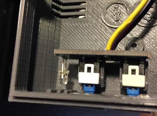
- Examine the 3mm Red LED and note that it has two leads, one short and one long. Then examine the Front Panel PCB and note that there is a line next to one of the holes.
- Insert the 3mm Red LED into the Front Panel PCB so the short pin is inserted into the hole with the line through it.
- With Front Panel inserted in the Mini NES Case, adjust the 3mm Red LED forward so it touching the 3D Printed LED Indicator Lens.
- Use a solder iron to attach the 3mm Red LED to the Front Panel PCB.
- For added measure, you may wrap the 3mm Red LED in Black Electrical Tape to stop any light from leaking into the rest of the case.
Set the Front Panel aside for now, do NOT glue into the Mini NES Case yet.
USB Extender
- Use a cutter to split the 10 Wire Ribbon Cable apart into a 6 Wire Ribbon Cable and a 4 Wire Ribbon Cable.
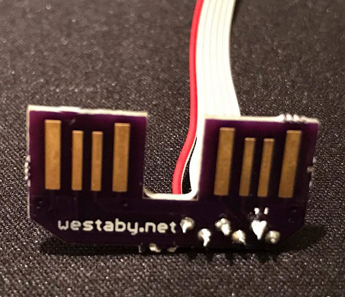
The 6 Wire Ribbon Cable will be used to make the USB extender. The 4 Wire Ribbon Cable will be used for the NFC reader later. - Strip one of the ends of the 6 Wire Ribbon Cable.
- Use a solder iron and attach 6 Wire Ribbon Cable to the USB Extender PCB, note the colors used and the wire labels on the PCB.
- Install the USB Extender PCB into the Raspberry Pi's USB port, then wrap the wire below the Raspberry Pi.
Ensure that the Ribbon Cable stays flat so it can be installed in the case.

- Wrap the Ribbon cable around the edge of the Raspberry Pi next to the SD Card Slot, see photo.
- Install the Raspberry Pi into the Mini NES Case.
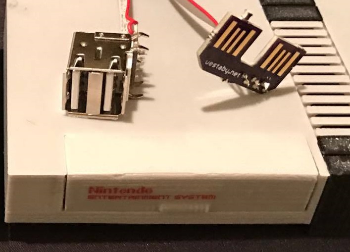
- Install the USB Socket into the USB Socket PCB, and install both into the Mini NES Case.
- Measure and trim the excess Ribbon Cable so all wires will reach the pins on the USB Socket PCB. Leave yourself an extra 1/2 inch (12mm) of length to strip.
- Remove the USB Socket and Raspberry Pi from the Mini NES Case.
- Strip the other end of the 6 Wire Ribbon Cable.
- Use a solder iron and attach 6 Wire Ribbon Cable to the USB Socket, using the USB Socket PCB and your color notes to match the wire labels on the PCB.
The USB Extender is now assembled. You may re-install the Raspberry Pi into the Mini NES Case.
Tip: If you get an error while uploading, check your libraries then try the suggestions here to fix. You can also copy paste the error message into google for advice.
Arduino Software
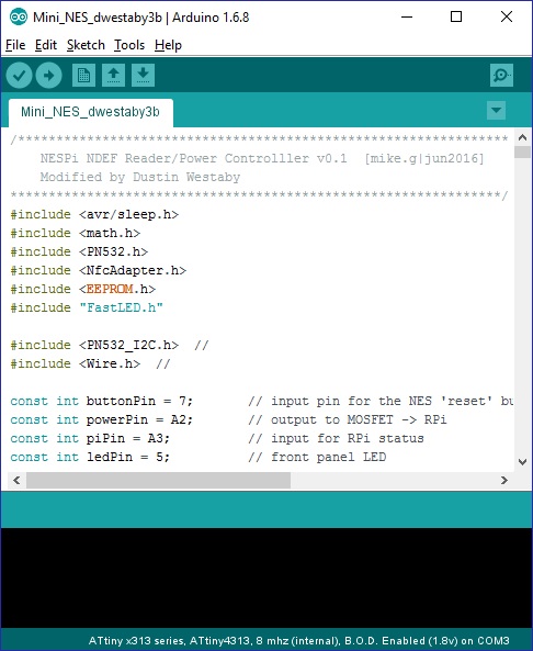
The next step is to upload the .ino sketch to the Arduino. If this is your first time working with Arduino, take a moment to follow some of the getting started tutorials. Follow the instructions for Leonardo.
- Download and install the Arduino IDE.
- Download the NESPi project zip.
- Install the Libraries to the Arduino IDE. If you have trouble, follow the Manual Installation steps.
- Open the NESPi.ino file in the Arduino IDE.
- Connect the Arduino's USB to your PC.
- Select Leonardo from the Tools>Boards menu.
- Click the Upload button.
- If you did everything right, it will take a few minutes to compile and load. After programming you should see the RGB Status LED light up.
- Your Arduino is now programmed, unplug the USB.
Tip: If the Status LED does not light up, disconnect the USB power and check your soldering. Then try again.
Arduino Hardware
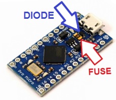
Before the Arduino can be attached to the Main PCB, it needs a small modification to allow enough current to power the Raspberry Pi.
- Disable both the Fuse and Diode indicated in the picture by shorting it with a bit of solder or wire.
The Fuse limits the current output of the arduino to 500mA, and the Raspberry Pi needs much more. The Diode decreases the voltage just enough that the Raspberry Pi complains. These two parts were on the Arduino for a reason. They protect the Arduino from being powered backwards and protect your PC / power supply from your circuit shorting out. So don't connect your Arduino backwards to a battery, don't short out your circuit, and don't plug your Arduino into your PC after making this modification. If you do so, you run the risk of damaging your Arduino or PC or Both.

To install the Arduino below the Main PCB:
- Examine the Arduino and Main PCB bottom pin labels. When installed, the labels will match exactly.
- Use a solder iron and the pin header that came with the Arduino to attach it to the Main PCB.
When finished, the Arduino will sit flush below the Main PCB.
Raspberry Pi Pin Header
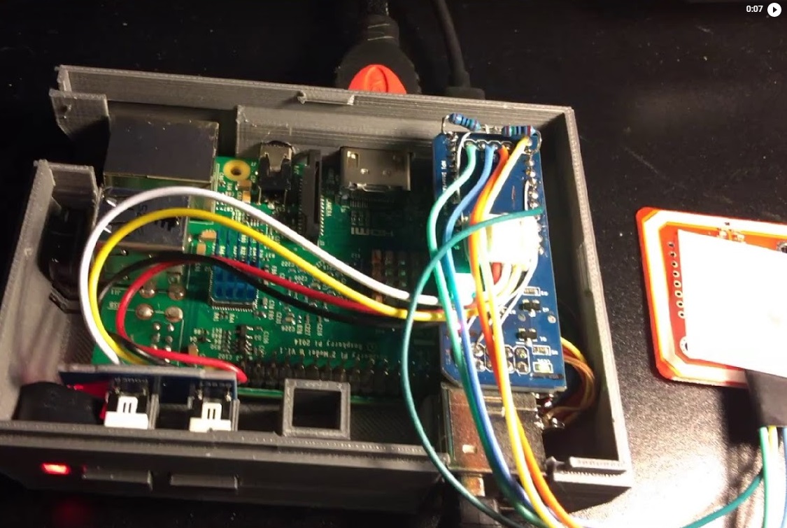
- Place the 2x5 Female Pin Header onto pins 1-10 of the Raspberry Pi, see photo.
- Line up the USB port of the arduino with the Mini NES Case opening and install on top of the pin header.
- The Arduino's USB will stick out the back of the Mini NES Case and slide over the 2x5 Female Pin Header.
- With the Arduino and Main assembly aligned in the Mini NES Case with the Raspberry Pi, use a solder iron to attach the Main PCB to the 2x5 Female Pin Header.
Front Panel Wiring
- Click in place the Quick Connector Cable into the Main PCB while noting the signal labels below the connector and the coorsponding wire color.
- Insert the Front Panel Assembly into the Mini NES Case.
- Measure and trim the excess length from the Quick Connector Cable, Leave yourself an extra 1.5 inches (40mm) length of wire.
- Use a solder iron and attach trimmed Quick Connector Cable to the Front Panel PCB, using your color notes to match the wire labels on the PCB.
- With the Raspberry Pi installed, you may now super glue the Front Panel Assembly into the Mini NES Case.
Tip: Remove the Quick Connector from the Main PCB if needed for positioning, replace after the glue has set.
 Click for Video
NFC Reader
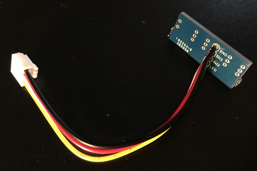
The PN532 NFC Reader module comes with a right angle 4 pin connector and 4 wires. Discard those and use instead the 4 Wire Ribbon Cable left over from making the USB Extender.
- Examine the PN532 NFC Reader and find the location of the I2C pins labeled: SCL, SDA, VCC, GND.
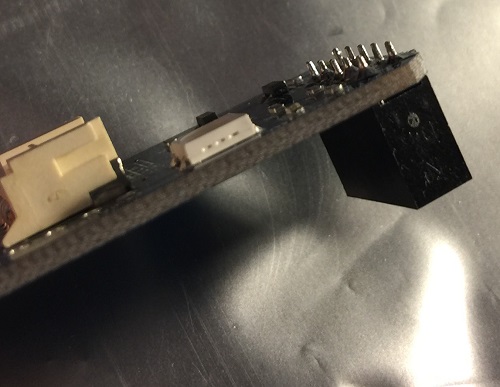
- Use a solder iron and attach the 4 Wire Ribbon Cable to the PN532 NFC Reader I2C pins, note the colors used and the wire labels on the PCB. Make sure that the wires sticking out the back of the PN532 NFC Reader are flush and flat. This is necessary for mounting the PN532 NFC Reader later.
- Measure and trim the 4 Wire Ribbon Cable so you have 4 inches (100mm).
- Use a solder iron and attach trimmed 4 Wire Ribbon Cable to the Main PCB, using your color notes to match the wire labels on the PCB.
Optional: The NFC has a sleep mode to conserve power. Marked on the back of the PN532 NFC Reader is the NFC Enable / RSTPDN signal. It is acceptable to leave this unconnected. However, wiring this pin will make the Electronics Kit a bit more power efficient.
To install, wire the NFC Enable pin on the PN532 NFC Reader to A0 on the Arduino / Main PCB.
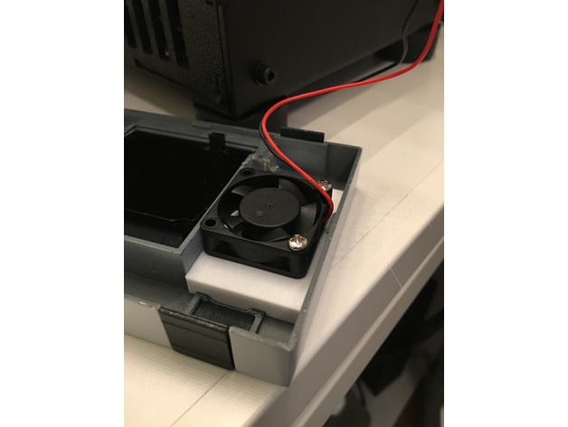
Cooling Fan
There are vents on the Mini NES Case, however, if you want to have play sessions of longer than a few minutes eventually you will want to add an active cooling fan. The Electronics Kit monitors the temperature of the Raspberri Pi and only turns on the fan when needed.
- Use a solder iron to wire the Fan into the Main PCB.
- The Red Fan wire goes to the + terminal and the Black Fan wire goes to the - terminal.
Your Electronics Kit is now assembled. Proceed to the Software Install page.
Congrats! Did you enjoy this guide? Please consider donating by paypal to paypal.me/dustinwestaby