NESPi Pi Control Electronics Guide
This is a electronics assembly and install guide for the Pi Control software developed by Jared Kirchgatter and Evan Wright, corresponding to the "Pi Control Rev 5 Easy Solder" Kit.
After completing this guide, you will have a working cartridge reader for your Mini NES and Web Control Interface, along with functioning front POWER RESET buttons, Power LED, and USB Socket.
If you have any questions, please post them to the Facebook Mini NES Builders Group.
Tip: You can find combo deals on Amazon for the Raspberry Pi, Heatsink, and Fan.
Note: OshPark is a PCB fabricator. They offer cheap PCBs with free shipping in about 2 weeks. Ordering from them will give you enough PCBs to make 3 Mini NES Cases.
Part List
Before we start you will need to make sure you have:
-
Recommended Printed Parts
- Bottom Shell
- USB shim (optional, helps with usb extender)
- LED guide/spacer (helps with LED alignment and spacing...not required)
- Embedded NFC tray with additional clearances
- No glue cartridge
- Daft Mike's original files (for the rest of the parts)
- Custom PCBs
-
Amazon Items
- Raspberry Pi 3 Model B Motherboard
- NES30 Wireless Bluetooth Controller or USB Classic NES Controller (optional)
- Heatsinks (optional)
- 25mm 5V Fan (optional)
- PN532 V3 (NFC Reader)
- Latching Push Button Switch (Power Switch)
- Momentary Push Button Switch (Reset Switch)
- Ribbon Cable (USB Extension)
- Dual USB Port (Front USB Port Style B. (Only fits the Style B Bottom Shell)
- MIFARE Classic 1K (NFC tag)
-
Ebay Items
- Micro JST Picoblade 1.25mm Pitch 4 Pin (Front Control Panel Pigtail)
- Micro JST Picoblade 1.25mm Pitch 6 Pin (NFC Pigtail)
-
Digikey Items
- A120924CT-ND - Ribbon Cable Connector (recommend 6 of these for mistakes)
- ED2986-ND - Front USB Port Style A
- 160-1139-ND - Front Panel Power LED
- S7076-ND - 16 Pin Pi Header Connector
- 455-1719-ND - 2 Pin 2mm Pitch Fan Connector
- NDD02N40-1GOS-ND - N-Channel Fan Mosfet
- CF14JT150RCT-ND - 150ohm Power LED Resistor
- CF14JT10K0CT-ND - 10kohm Fan Mosfet Resistor
- 1N4001-TPMSCT-ND - Fan Flyback Diode
- WM1744-ND - 4 Pin Front Panel Connector
- WM1746-ND - 6 Pin NFC Connector

Tools List
These tools are useful when following this guide. Approx prices are listed.
- Solder Iron ($30)
- 0.3mm Solder ($3)
- Flush Wire Cutters ($2)
- Wire Strippers ($5)
- Helping Hands ($8)
- Super Glue ($1)
Before you begin, watch this video on youtube to become a soldering pro!. Soldering is EASY. If that video is too long, you can learn from any of these videos in just a few mins.
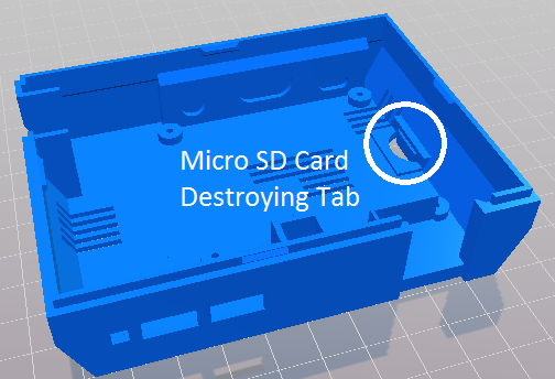
Remove the SD Card
Damage Warning! If you have an SD Card installed in the Raspberry Pi, remove it now!
The 3D Printed Case has a defect that will snap in half the SD card when the Raspberry Pi is inserted OR removed from the Mini NES Case.
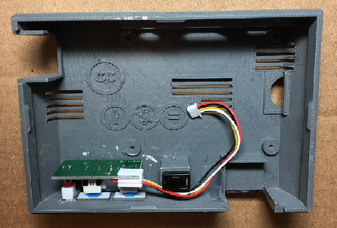
Assemble the Front Panel
Assemble the Pi Control (Main Board)
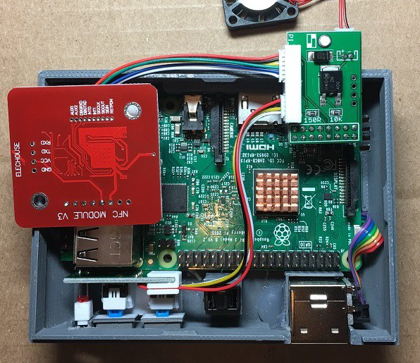
This PCB is designed to be as easy to solder as possible using all through hole components. The NFC and Control connector are very small connectors(1.25mm pitch) and require careful soldering to avoid bridging solder points. The connectors are meant to be inserted into the bottom side of the board.
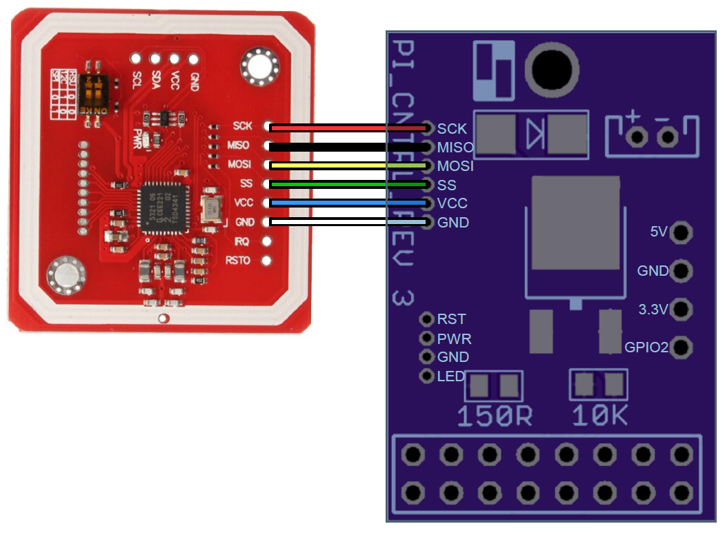
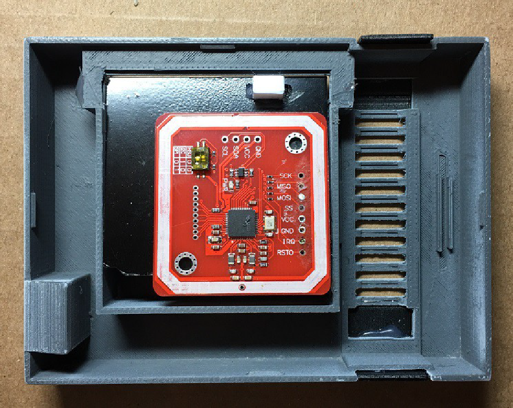
Wire the NFC Reader as shown below. The NFC Reader needs to be in SPI mode (DIP Switches).
Assemble the USB Extender
Installation Steps
The pictures shown use the Style B USB Port which may require the tweaked bottom shell design.
- Glue front control panel into the bottom shell.
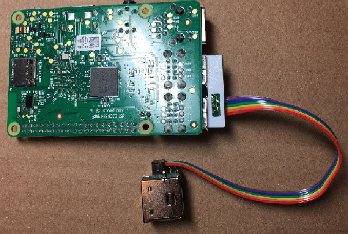
- Insert USB extender with printed spacer into lower USB Port of the Pi.
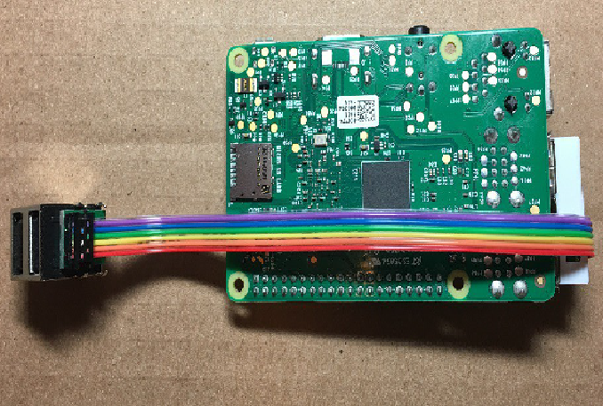
- Wrap the ribbon cable underneath the Pi.
- The ribbon cable should hug the edge of the PCB snugly for the best fit.
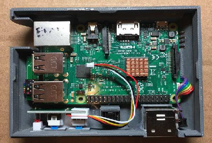
- Slip the Pi and front USB Port into the bottom shell (the SD card needs to be removed when installing and removing the Pi from the shell. (Glue the from USB port into place)
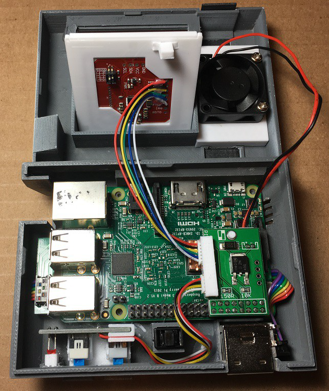
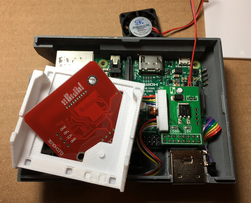
- Connect the front control panel, NFC, and Fan Harness to the Pi Control Board. Each connector only plugs in one way, be gentle.
- If using the slim 30mm fan mount, you will need to remove the white printed support trim from around the top mounted connectors. It is there to give the connectors support while inserting the wire harnesses and is not necessary.
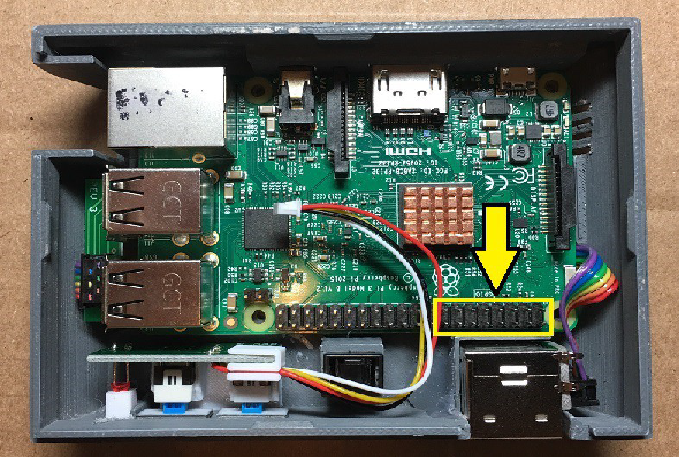
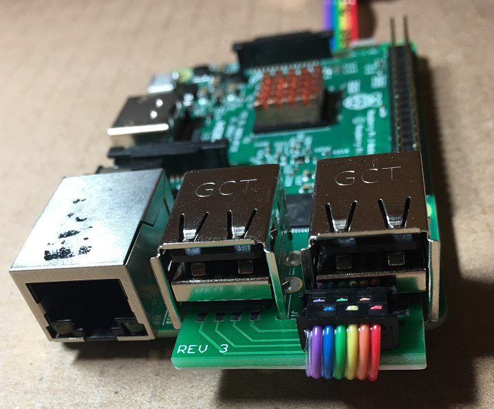
- Place the Pi Control Board into position
- Be sure to insert the Pi Control board into the right most pins of the Pi
- Check clearance between heatsinks and bottom of Pi Control board. If necessary remove white printed support trim from top mounted connectors or remove heatsink. If heatsink is too tall and touches any of the circuitry or exposed pads underneath Pi Control board you will need to use a shorter heatsink or none at all.
NFC Installs - Cart Tray
- If using the embedded NFC cart tray (highly recommended) insert the NFC through the bottom of the tray.
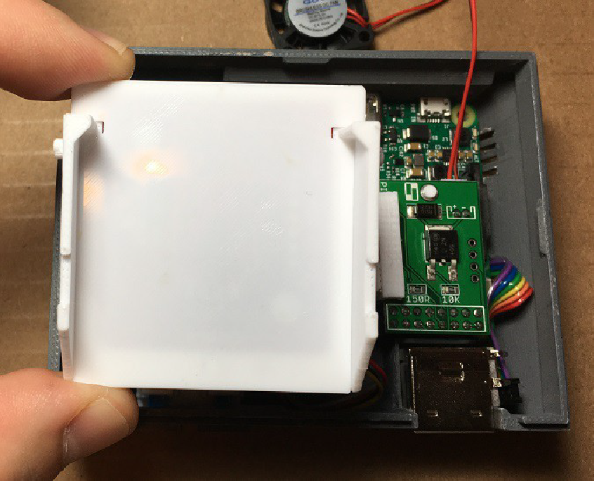
- Snap conver into place.
- Insert cart tray into top shell. It should flex enough to get one side in and then the other.
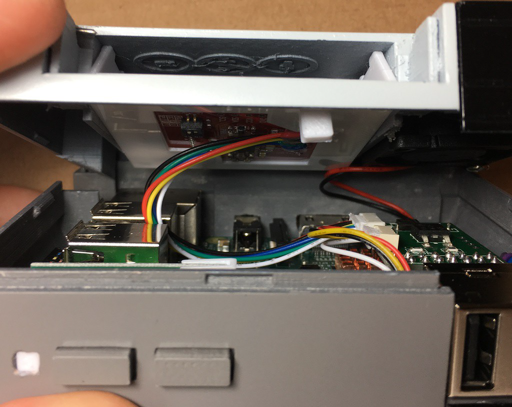
- Careful routing of the NFC harness between the two usb ports on the Pi as shown will result in the best fitment and pivot operation.
If you are not using the embedded NFC cart 3d part, the suggested placement of the NFC is shown here. It is a tight fit in the case.
Try gluing this in lightly and testing fitment before commiting to placement. Test "barbantia" latching operation.
Cooling Fan
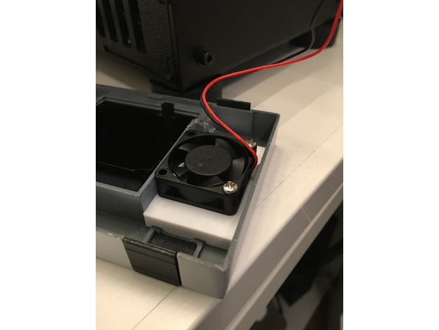
There are vents on the Mini NES Case, however, if you want to have play sessions of longer than a few minutes eventually you will want to add an active cooling fan. Wire the fan into the Raspberry Pi power, it will be always running.
- Your fan is plug and play into the 2mm Pitch Fan Connector.
- Test the fit of closing the case with the fan installed. You may have to trim the length of the fan's wires.
- Mount and glue as shown in the picture.
Raspberry Pi Software
With the electronics wired into the Raspberry Pi, you can now install the Pi Control software to your RetroPi. This will enable the Web Control Interface, NFC Reader, POWER RESET Buttons, and Power LED.
Warning!!! Installing the Pi Control Board on the incorrect pins on the Pi can damage your Pi!
- Configure keyboard if not already done
- up, down, left, right, start, select, a, and b are enough for now
- In settings, connect to local network, choose “SHOW IP” and make a note of the IP address given to your Pi.
- Press F4 on the keyboard to exit to the terminal.
- Download and extract Pi Control archive
sudo apt-get update
wget https://github.com/jetechteam/picontrol/raw/master/picontrol.tgz
tar -xzf picontrol.tgz
- Run installer
cd picontrol
sudo sh ./setup.sh
- When prompted to reboot type “y” and hit enter.
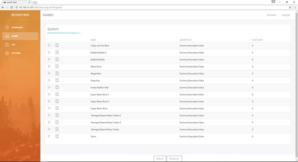
- After reboot you may now access Pi Control web app from any browser connected to same local network by typing in the IP address of the Pi.
- Example: 192.168.1.25
- Default Username: picontrol
- Default Password: password
(The NFC reader has set of switches that must be configured for SPI communication)