Guide: Boba Fett Chest Display
Hello visitors from the future! This guide is slightly outdated. I recommend checking https://westabyelectronics.com/store/tutorials for the latest guide.
Below is kept for historical purposes.
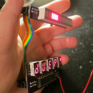
If you are making a Boba Fett costume, the display on the chest piece can be especially troubling. Outside of a one or two available on thedentedhelmet.com, there isn’t a lot available. Leaving a builder to come up with alternate displays. Such as using a decal or placing a light behind a printed graphic on transparency sheet. Cheap and it looks ok, but is not animated. An animated display is much more appealing.
In this guide, we will go over how to create an animated display for the boba fett’s chest armor. You will need at least beginner soldering skills to complete the circuit. All the parts add up to less than $40.
Tools:
- Solder Iron & Solder
- Wire Cutter
- Solder Wick
Part List:
- 2 – Red LED Bargraph Displays
- 5 – Red LED 0.3″ CA 7seg Displays
- 5 – 33 ohm resistors
- 5 – 1k ohm resistors
- 5 – NPN Transistors
- 1 – 1uF capacitor
- 1 – 10k ohm resistor
- 1 – AA Battery Holder w/ Switch
- Some wire (to connect the boards)
You can purchase all the above from mouser, use this link for a ‘one click purchase’ part list: https://www.mouser.com/ProjectManager/ProjectDetail.aspx?AccessID=7c6a316116
Lastly, you will also need the two PCBs and a programmed chip. I sell the custom parts for cheap. Email me for details. thatdecade@gmail.com
Alternately, if you have means to program chips yourself (arduino), you can purchase the custom parts yourself. Source code can be found on codebender.
Assembly:
Once you have gathered all the parts, you can begin putting it together. Start with the bargraph board.
- Examine a bargraph display part and look for the small notch in one corner, this marks the anode side.
- Examine the bargraph display PCB. With the bargraph picture side facing you and the 6pin connector on the left, the top is the anode and the bottom is the cathode.
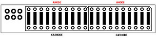
- Solder the two bargraphs into place, being careful to install right side up. They will not function is installed upside down.
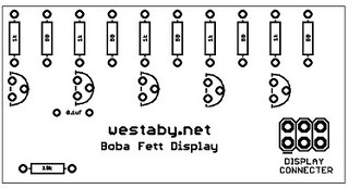
Next is to solder the rear parts on to the main board.
- The row of ten resistors at the top are labeled 1k and 50. The part list does not include 50 ohm resistors. Instead any value from 33 to 47 may be used, lower is brighter.
- Solder on the 5 x 1k ohm resistors to the spots marked with 1k.
- Solder on the 5 x 47 ohm resistors to the spots marked with 50.
- The next row down are the transistors. Orient the transistors so the flat side faces the same way as pictured. Solder them in place.
Optionally, after inserting each transistor into the board, you can fold it down flat against the board before soldering. Thinner circuit is easier to install in your chest piece. - The remaining two parts are the capacitor and 10k resistor. Solder in place where indicated.
- Clean up. Turn the board around and clip the excess leads off.
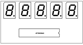
Now to solder the front parts on the main board.
- Examine a digit display part, look for the small notch. This marks the orientation.
- Insert each of the 5 displays, but do not solder down yet. Double check that they are inserted right side up. They will not function is installed upside down.
- You may now solder the displays. The solder points are between the resistors on the other side. Use the solder wick to clean up any unintentional solder connections.
- The final part to go on the front of the main board is the chip. Again, note the notch for the orientation.
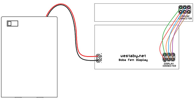
Last is to wire the two boards together and power up.
- Figure how much space you need between the two displays.
- Examine the area on each board labeled display connector. The line next to one of the pins indicates orientation.
- Cut 6 wires to cover the distance between the connectors adding an extra inch for positioning.
- Solder each of the six wires, positioning pin 1 to pin 1, pin 2 to pin 2, and so on
- Connect the battery pack, the wires are color coded. Red goes to +, Black goes to -. Do not mix these up, you will destroy the chip.
Power it up and enjoy!