-
Mk3 Boba Fett Range Finder
The evolution of the Boba Fett Range Finder prop continues with the introduction of the Mk3 design. Building on the success and feedback from the Mk2, the Mk3 brings a significant change in the accelerometer integration, aiming for a more streamlined and efficient design. Sales: https://www.etsy.com/shop/WestabyElectronics Integrated Accelerometer: A Leap Forward The most notable change in the Mk3 design is the integration of the accelerometer directly onto the main circuit board. This eliminates the need for soldering two separate circuits together, as was the case with the Mk2. The decision to integrate was driven by both cost and design efficiency. Two years ago, the cost of soldering the accelerometer chip…
-
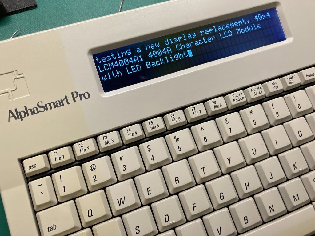
Alphasmart Pro Mods
Back in 2021, I started work on an embedded word processor based on a Teensy dev board. My design was based on a 40×4 character LCD, sd card and usb host to plug in a keyboard. Editing was limited to typing and backspace. Arrow key support was limited to reviewing previous text, not editing. Worked well enough, but I halted development when I got my hands on an old AlphaSmart Pro. I remember using the AlphaSmart with great success in the late 90s. So I seeked one out on ebay, so I could benchmark the features on my own embedded word processor. I found no hotkey support and a broken…
-
Boba Fett Chest Display Circuit: An In-Depth Analysis
A breakdown of the glowly lights on the front of boba fett's suit.
-
Hot Glue gets a Bad Rap
In this post, I’ll detail how I use hot glue and make instant setting joints that are stronger than I can break apart by hand. I use hot glue for almost every 3d print that I need to glue. This video is a good watch for background info on glues. In summary, hot glue is fast, easy, and a great gap filler. It will let you down on smooth and cold surfaces. Let’s fix that.
-
3D Printer Music
I was working on a custom script to automate knocking parts off the print bed into a tray so I could easier manage remote prints when I stumbled on the musical features of g-code. Here are my references: Teach your 3D Printer to Sing and Dance Online MIDI Editor .midi file to G-code Converter See it in Action! Here is my g-code. Copy to the end of your Printer Settings > Custom G-code > End G-code in your slicer.
-
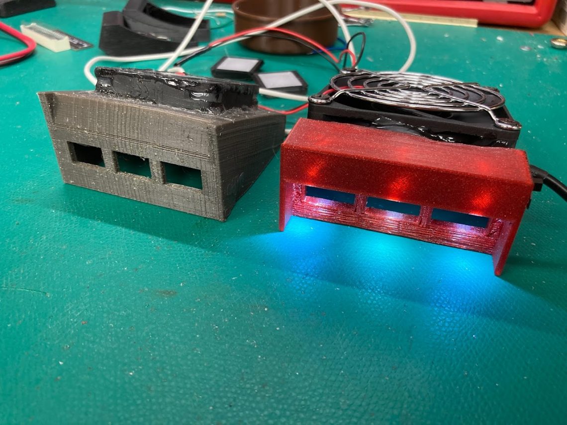
Solder Fume Extractor
Back in 2018 when my kid was born, I got serious about air purifiers and fume extractors in my workshop. I designed my fume extractor using spare parts and a cheap mini filter meant for a smokeless ashtray. It is finally time for an update. Here is my 2022 fume extractor!
-
Mk2 Boba Fett Range Finder
The Boba Fett Range Finder prop with lights comes in two varieties. Switched on by a microswitch in the helmet stalk, or a tilt sensor in the range finder. Sales: https://www.etsy.com/shop/WestabyElectronics My initial design used the latter. For shipping reasons, depending on your country, a ball or mercury tilt sensor was included with the Mk1 Range Finder. However, I do not like either of these options. The ball can get stuck, and mercury has shipping restrictions.
-
Business Cards and Email Address
So, you wanted to contact me for a commision, rental, or just to chat. You dutifully entered the email address from my business card and then BOUNCE, no such address??
-
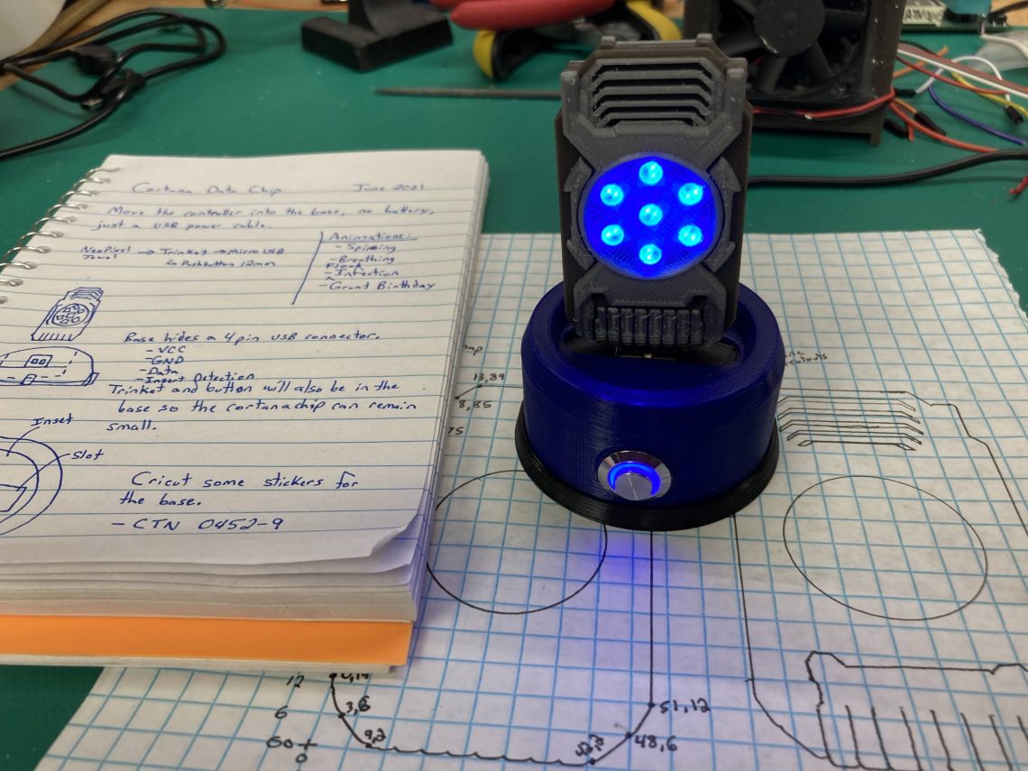
Cortana Data Chip and Display Stand
I get asked to make more cortana chips from time to time, but the partnership that allowed me sell resin casted props is long over. I have been wanting to redesign as a display piece using a more modern neopixel lighting for the animations.
-
Bookmark Flashlight
This is a bookmark sized flashlight with paths etched for copper tape. The CR2032 battery pack folds around the back. Files are on thingiverse: https://www.thingiverse.com/thing:4798489 Part List: Copper tape with conductive adhesive backing. https://www.adafruit.com/product/1128 CR2032 battery holder with on/off switch. https://www.adafruit.com/product/783 CR2032 lithium batteries. https://www.adafruit.com/product/654 SMD LEDs https://www.ebay.com/sch/i.html?_nkw=smd+led+0805 SMD Resistor 390 – 510 ohm https://www.ebay.com/sch/i.html?_nkw=510+ohm+resistor+0805 Printing Download the files from thingiverse. Start with the .scad file in OpenScad. Modify the print height variable to match your printer. The battery clip is attached by a hinge that must be a single layer high. Render and save the stl. The bookmark and battery glue tabs is about 9 inches long, I rotated…