Star Trek TOS Medical Scanner Prop (Mk1)
This article is about a prop medical scanner I made.
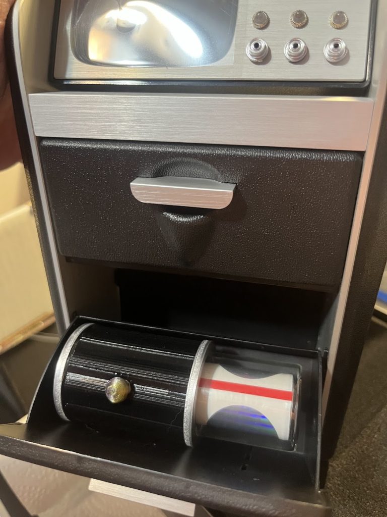
The Wand Company tricorder has a big empty compartment and inspired a bunch of hand scanner builds. Over the last year I watched a bunch of inspired makers with new designs show up, each with its own flair. I had my own ideas.
Overview
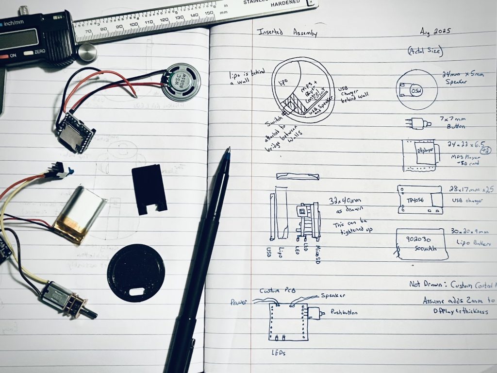
There is a lot going on inside this prop. I designed a custom PCB and a 3D printed internal assembly so everything is located, supported, and wired correctly.
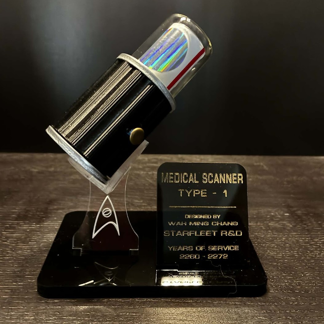
- Top Spinner: the rotating white cylinder with the red stripes and holographic bits.
- Inner Assembly: 3d print that holds the battery, motor, PCB, and speaker.
- Outer Body: 3d print that covers the inner assembly, and provides a solid surface for the flexible grip.
- Bottom Covers: two interchangeable covers that hide the USB port and microSD slot.
Physical Constraints
The Star Fleet Technical Manual has some good references of the physical dimensions for the medical scanner (page 129). Says the max diameter is 35mm with a suggested length of 60.5mm. The Wand Company tricorder empty compartment is happy with scanners in that diameter range, and it has room for longer items.
Here are my intentional deviations:
- The length is 80mm to house the sound circuits.
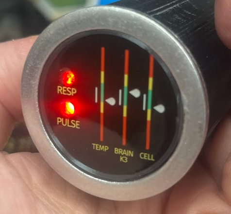
- I took liberties with the bottom display design so the animated lights read better and I added a second aluminum ring.
Electronics
- DFPlayer + microSD card
- TP4056 charger module w/ USB-C
- 500 mAh LiPo
- N20 geared motor
- Self-animated LEDs
Circuits
Power Wiring: Battery -> TP4056 -> Custom PCB -> Motor/Lights/DFPlayer
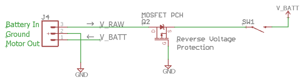
The LiPo has its own protection circuit. The TP4056 module provides USB-C charging and additional protection. The charging port is behind the lower cover.
I still need to measure battery life properly in real use. Mk1 is functional, and I assume the battery life to be around 1-2 hours.
Sound effects
The mp3 is from STAR TREK: SOUND EFFECTS – OST 1988, track 62 Hand Held Medical Scanner. The original clip starts quiet, so I trimmed and rearranged it so the interesting part hits sooner.
Custom PCB
I used OSHPark for my boards. Gerbers are available here: DFPlayer Auto Play Circuit
If you order that PCB, the DFPlayer autostart details are explained in this post.
PS: if you want a PCB but do not want to deal with ordering, you can email me. thatdecade@gmail.com
Spinner Assembly
I reviewed clips of the show and counted frames between rotations. After a bunch of overthinking, I landed on 150 RPM as the right spin rate for the vibe.
The gearbox motor drives a 3d printed cylinder topped with an aluminum disc and wrapped with white vinyl tape to hide print lines and defects.
That vinyl wrap feels like cheating lol. It gives me a smooth surface fast. Not perfect. A few bumps and tape lines still show. So I strategically position the red vinyl tape and hologram stickers.
The end result is a near-flawless spinner assembly that looks great through the glass.
Grip
The hand grip is 3D printed TPU. Printing with 1 wall and 0 infill makes it surprisingly flexible and pleasant when squeezed.
I tuned slicer settings until the print head made as few travel moves as possible. Printing can leave junk material and strings in random spots. I typically clean this up with hot air and pliers, but that doesn’t work with TPU. It is too tough. Reducing travel reduced the random deposits, which made the grip look cleaner.
Bottom
The prop includes two bottom covers, held in place by magnets.
Cover 1: Plain and functional. Protects the USB and MicroSD slot.
Cover 2: Graphic, Glass, and Metal
My first prototype used poured resin over the graphic. It photographed fine. I shared build photos online and people seemed into it. But in person, I did not like it.
So I switched to watchmaker glass that fits inside the aluminum ring, plus a tiny 3d printed gasket to keep everything aligned.
The final version is a stack of plastic + aluminum + printed graphic + glass.
Lastly, the LEDs are self-animated
- One blinks at 1 Hz to simulate heartbeat scanning.
- One slow-fades in and out to simulate respiration scanning.
Assembly and serviceability
The inner printed assembly and outer printed shell slide over each other and screw together using heat-set inserts and screws. The TPU grip covers the whole body.
The TPU placement is the point of no return.
I use a metal tool to stretch the grip and slide into place over the power button. Once installed, I cannot re-stretch it enough to remove cleanly. If repair is needed, the grip gets cut off and replaced with a new one.
Mk1 Annoyances to be fixed in Mk2
Speaker Acoustics
The sound is good but way quieter than I wanted.
I used a 2W speaker and opened vent slots in the outer shell to let sound out. That all sounded fine during testing but was totally dampened when fully assembled.
I did some research on this and came up with two fixable issues:
- The front and back of the speaker share the same air volume. See wikipedia loudspeaker design for cancellation effects of open baffle designs.
- The slots are covered by the side grip, so the open area is not actually open.
I am pretty sure I can fix this by adding a resonance chamber for the speaker so the front and rear waves are separated and a real exterior vent so the sound can actually get out.
Motor Rattle
Since the sound effects were quieter than my testing, the motor noise was also revealed and became problematic. The motor was louder than the sound effects, whoops.
I have a hypothesis that the gearbox needs lubrication and the motor is mounted too tightly to the inner assembly.
For Mk2, I’ll start with dry lube and if that isn’t enough, I can also add a soft anti-vibration gasket. Hoping the motor noise is reduced.
Files, costs, and where to find updates
Watch Printables for future uploads, including Mk2 files and BOM when ready.
WestabyElectronics on Etsy for listings.
The first one cost about $280 to make. Most of that cost is the hard-to-source parts and the time spent on each assembly.