Cybiko Backlight
This tutorial will help you modify your cybiko so it is backlit. Never be in the dark again!I got the idea to do this after seeing another person showing off in the forum.
Note: I can’t recommend enough that you take your time and read this entire DIY before beginning. Doing this will forever change your cybiko with the potential to destroy it forever or worse permanently disable communications.
Things needed:
- EL kit can be found from http://store.yahoo.com/e-clec-tech/ (I purchased the small panel experimenter (static) kit and it was more than large enough for this project)
- Screw driver small enough to open the cybiko and remove all circuit boards inside.
- Solder + solder iron
- 12 in of Weather stripping (clear thin plastic that can be found at most hardware stores, sells by the foot)
- Electrical tape
- A short stretch of wire.
- Goo gone or some kind of adhesive remover (like nail polish remover)
- Glass cleaner
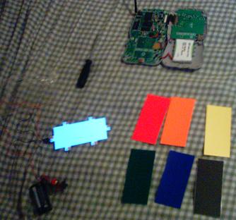
I am really impressed with the final product of this project. The cybiko xtreme is now slightly thicker but the light from the EL panel is so even I love it! You can see in this picture the EL kit came with several overlay stickers to change the color of the panel. Without the overlay (the way I did mine) it is a bright blue when on and a grayish pink when turn off. Once placed behind the LCD the turned off color is much darker. My advice, don’t apply an overlay until you see how it looks both on and off behind the LCD.
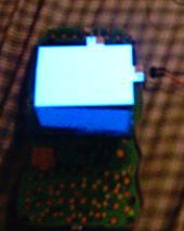
Once you have the cybiko open and all screws removed you will be able to see the LCD up close.
I also recommend that you remove the vibration motor and the battery. So the circuit board is not tethered to the back casing while we do our work. The motor is screwed down but also has some glue on it. You should be able to remove the motor with moderate pressure. The battery has the same low tack glue on the back of it as you will find on the back of the LCD. You can remove the battery by working it back and forth till to pops out. I reused the glue on the back of the battery to put it back in later by placing a piece of wax paper on the glue now. You don’t have to do that you can reattach the battery with tape. Also if you have a new set of batteries laying around now would be the time to replace them because we will be super gluing the case together.
One more recommendation. You may have noticed that once you have the cybiko removed the “link activity” light insert is very small and doesn’t stay in the casing well. You can super glue this in and you won’t have to worry about losing it later.
What you have to do next is remove the LCD from it’s plastic casing. There is a low tack glue spread across the entire back of the LCD. Slowly wedging it back and forth you should be able to remove it without cracking it. I’m sure you’ve seen cracked or leaking LCDs, it’s not pretty so take your time. Once you have the LCD removed you will notice that it is connected to the circuit board via a flat cable along the bottom. You don’t have to but you can remove the plastic LCD housing from the circuit board be squeezing the tabs on the other side (this will make sizing the EL panel easier). You should also go ahead and peal the silver backing from the LCD.
Next step is using goo gone or some kind of adhesive remover to wipe down the LCD and the LCD housing.
Once everything has no tack left to it you can use glass cleaner to remove any fingerprints from the LCD front and back. Also wipe down the top half of the cybiko inside and out with glass cleaner. Do this after every time you touch anything and before you put it all together. We are fighting dust and smudges here. The fact of the matter is you WILL leave visable dust on the screen no matter what, but how much dust is up to you.
The next thing we need to do is size the EL panel for our uses. You will notice that there is a lip around the LCD casing that the LCD fits into. You can begin cutting the EL, just make sure that it fits inside of that lip. You can see that there is several small stretches in the casing where there is no lip, this is where the terminals will stick out. Size the panel so that just one of these terminals sticks out of the casing. The picture shown is before I finished cutting the panel but once finished the terminals on the right are the only ones left. The EL panel should extend out of the casing and to the edge of the circuit board. The terminals should extend past the circuit board, we will bent these over so that we can plug the panel in from the back.
(Right) Same pic as above but with the front plate put on as a “dummy run”. This pic was taken before I finished sizing, the EL in the finished product does not extend past the circuit board.
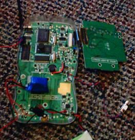
(Left) You can see in this picture four things. One, the solder points used to get the power to the EL panel. You should be able to solder these wires in quite easily, the solder points are pretty big. Just make sure that the you don’t short the battery or it will near instantly die. The inverter requires the correct polarity so be sure that the red wire goes to the (+) terminal and the black wire goes to the (-) terminal. Two, the inverter circuit included with the EL kit. You can see that I wrapped it in blue electrical tape* so not to short anything when I repackage thing back together. Three, I cut the inverter kits included wiring to make the wire pair between the inverter and the panel was just long enough that I could reposition the inverter if I wanted to. I removed about 4 inches of wire. Four, you also want to want to wrap the EL panel terminals in electrical tape. You can attach and wrap the panel socket with electrical tape as well.
*Wrapping the inverter chip is a 3 step process. First wrap in electrical tape, then wrap in aluminum foil, last another layer of electrical tape. This prevents circuit shorts and interference with the antenna.
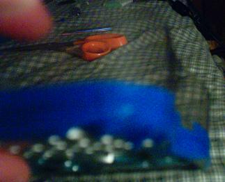
You can see in this picture how I attached the weather stripping. I cut the weather stripping so I had two perpendicular cuts 1/2 inch apart from each other (can’t trust the cuts from the factory as straight). I chose this width because it still felt great when I held my cybiko and it was just wide enough that I could fit the inverter in the “sandwiched” casing.
Then cut in slits to the edges so it fit up exactly to the cybiko casing front half. You also want cut a hole large enough to use the switch included with the EL kit. You can super glue the switch in after you put the circuit board back in (not yet).
Using a lot of super glue and electrical tape to hold it in place while drying I was able to attach the weather stripping. The super glue does not bond instantly because of the type of plastic but takes 10 to 20 min. That is why I used tape to hold it together until it dried.
Once you have it attached to one side of the casing it’s finally time to put everything back inside. Before placing the main circuit board back inside your should wipe it down again for fingerprints. It’d be real annoying to have it all put back together then notice a finger print or a spec of dust on the LCD and have to pull it all back apart.
If you’ve lost any of the small black screws like I did you can use the silver screws from the outer casing to secure everything.
Note: If at any point you accidentally removed flat cable that connects the two circuit boards. You should be able to gently pull out the connector terminal and push the cable back inside, then gently wedge the connector terminal back closed.
Once you have all boards screwed down you will notice one HUGE problem, there is nothing attached to the antenna! I solved this by soldering a loop of wire to the pressure contact then wrapping the loop around the antenna spring. This will allow wireless communication and still allow you to spin the antenna around as much as you want.
As you can see in this picture the final gluing did not require as much tape.
Ok your done so here’s a follow up for this project.
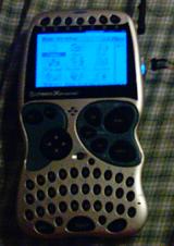
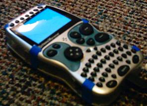
The new thicker design is no harder to fit in my pocket, though with the current placement of the back light switch it sometimes catches on my pocket, so it may have been a better idea to place it towards the top. You can see the current placement of the switch in the picture.
As you can also see from the picture I spray painted both the sides and the faceplate. It is a few shades lighter then the original color and makes the new design just look great.
Q/A:
Q: Could the switch be placed on the front?
A: Adding the switch to the front would be near impossible because there just isn’t enough room there. But I also theorize that a surface mount switch would just barely fit. Only problem is they only exist as momentary contact switches. Think the light is only on when you press the button. I don’t recommend this given this analogy. Ever try to program your backlit watch? You press the light button to see where you are then press a few buttons blindly. Then light it up again. Your always working in the dark.
Q: Will this work for my classic?
A: Sure will. I won’t go into it because I only had one inverter so my left over EL is worthless. But I originally got the idea of using EL panels to backlight the Xtreme from a guy who back lit his classic. He didn’t use a switch do it so the cybiko had to be on/charging constantly. He mounted the inverter externally on the top where it fit nicely next to where the stylus comes out.
Q: Is there any way I can add a back light without “super gluing” it thicker (without radical case modification)?
A: Well you can mount the inverter externally. The reason I had to “thicken” the device was so I could mount the inverter where it couldn’t easily be damaged. But if you wrap the inverter in electrical tape then super glue some of that weather stripping plastic around it you can make a very sturdy case for it. The inverter circuit has 4 wires going to and from it. You can reduce this to 2 wires if you make the batteries external as well (the kit comes with a battery mount already attached to the inverter). If you were to tie those to a male and female connector cable you could have a small cube you could plug in and have the back light turn on. This method would eliminate the need for a switch, but if you still wanted one you could mount it onto the inverter casing. (Relative size of the inverter, cut a AAA in half length wise, the inverter is little thicker then that) This is the best idea for external mounting it next to making the inverter permanently attached to the back or top of the Xtreme.
There is one more option but it is very complicated. It involves replacing the inverter circuit with a surface mount (SMD) chip. The chip is so small it could easily fit anywhere inside of the cybiko xtreme. But it is so small it requires special methods to solder to it. I’ll edit this page with more information when this becomes a more obtainable solution.
Q: Can the back light come in any other color then white/blue?
A: Whitish blue is just the default color of the EL panel the EL panel kit comes with “An assortment of color overlays.” Which I found to be black, orange, red, yellow, green, and blue. The black, green, and blue are just too dark so it would be very hard to use the cybiko when the back light is turned off. So that has us left with red, orange, yellow, and whitish blue. Personally I am doing this for a friend right now that has painted his faceplate, antenna, and expansion slot insert bright orange and wants me to add a back light to it that is also orange. I don’t for see any problems.
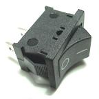
Q: If you could do it again what would you do different?
A: Well I would still have mounted the inverter circuit internally, but I would have used a different switch. I was thinking a low profile rocker switch would be nicer than the slider switch that came with the EL kit. Here’s a picture of what I would use.