LED Rail Blade Assembly
This guide will walk you through assembling LED strips to place inside an electronic sword prop.
TOOLS AND MATERIALS
- Spool of unshielded bare wire
- Few feet of shielded wire
- Solder Iron
- Solder (0.5 oz is plenty)
- Wire Snips
- Needle Nose Pliers (optional)
- Hot Glue or Clear Packing Tape
- Safety Glasses
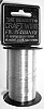
You can use any bare wire you like, but I found that steel craft wire works best (pictured). It is strong, thin, and does not need to be stripped.
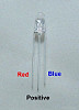
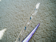
Take a close look at one of the LEDs. You will notice that at the base of the plastic there is a flat edge. This identifies the red wire.
The hardest part of the blade assembly is keeping straight which side is which because all the LEDs must connect the same wire to the same rail. I suggest bending all the wires on the LEDs before you start soldering in such a way that you can easily check which wire is red and which is blue. For me, I bent the positive wire straight down and the two side wires straight out. When I hold the LED with the positive wire facing down and the LED pointing towards me, the red wire will be on the right.
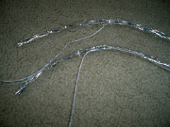
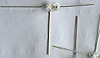
Unroll three lengths of about 35-40 inches of wire (we will snip this down later). Use weights and tape on either side to suspend two of the wires. You want to suspend it the approx. length of one dangling LED wire so when it sags from the weight of the LEDs it does not have far to fall. We want the suspended wire tight and remain straight. See the picture below for the spacing between the two wires (a little larger than the width of a LED).
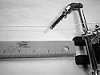
Lay a ruler down below the wire. We will use this to align the LEDs and be certain the spacing is consistent.
Note:
You can use any spacing you like, but you have 60 LEDs for two 30inch blades. A spacing of 1 inch seems appropriate.
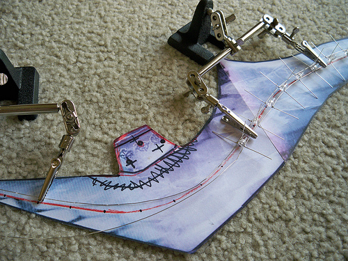
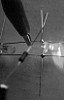
In the picture I am using a tool called “helping hands” to hold my wire. I bought mine from Menards for ~$5.
Warm up your solder iron and solder the LEDs to the single rail, but do not snip any of the leads yet. You can start with either the red wire or the blue wire, but we will do the positive wire last.
For soldering the last few LEDs to the second rail, I brought the wires down from the suspension. The two rails were too far apart.
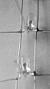
Before you go onto the positive wire, this is a good time for touch up. The more solder you put on each joint, the “stronger” it is. These blades will probably get knocked around, so we want these joints strong. You can see in the picture the old quick and dirty joints (left) vs the new stronger joints (right).
Test:
If you are not confident in your creation, you can also test things at this point. The wire unconnected is positive, the two rails are both negative. Use a resister between a 9V battery and the LEDs. BEWARE: At this voltage, one slip of the hand that exposes the LED directly to the battery will destroy the LED.
What I do is clip the battery negative to one of the rails then drag the resister across the positive wires, testing each LED in the row. Repeat for the second rail. If something doesn’t light or lights the wrong color, it is easier to fix now than later.
Once you are confident, clip off the extra wires on the two rails and prepare to solder the resisters onto the positive wires. If you did a good job, the rails should not be much wider than the LEDs themselves.
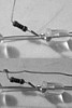
We need to solder the resisters between the positive wire and the positive rail. The picture shows the steps of soldering the resisters and the positive rail to the structure.
Be sure that there is a gap between the positive rail and the positive wire. You can see in the final picture how close they are. If for some reason the blade was squeezed and these two wires touched, the LED would be destroyed.
You can either trust the gap or try to seal the gap with hot glue or a piece of clear packing tape (has to be thick enough so it can’t be punctured by the sharp edges).
Clip the stray wires (don’t want any shorts) and connect the bottom of the rails to a battery to test. The entire blade will light up red or blue with each connection.
The last step is to cut the blades into 5 sections. I am assuming you used 30 LEDs in each blade, so each section will consist of 6 LEDs. Cut the blue wire between each section.
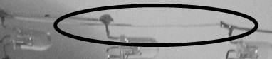
ONLY section off the blue wire, the red and positive wires will run the entire length of the blade.
You can see in the picture the new gap between the blue rail sections and the shielded wire soldered to the section. Each section will have its own wire.
Use the tape or hot glue to bunch the wires and keep them from becoming tangled.
Note:
It is a good idea to use a marker and label the wires. One dot for the top of the blade, 5 dots for the bottom, 2/3/4 dots for sections between, dash for the positive wire, two dashes for the red wire.
The final blade will be pretty flimsy depending on the type of unshielded wire you used for the rails. This allows it to be gently bent into the curve of a blade. After shaping the LED rail to fit your blade interior, wrap in packing tape to strengthen the rail shape.
Finished: