-
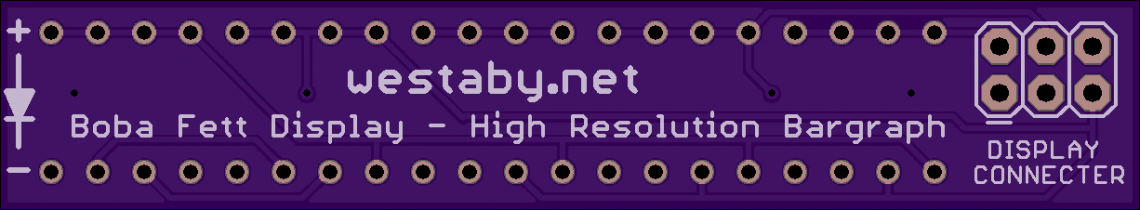
Upgraded Boba Fett Chest Displays
Dec 2020 brought new episodes of the Mandalorian which blessed fans with the reappearance of Boba Fett and his faithful armor. The chest display refresh gets me excited. Instead of a blocky bargraph lightshow, we get a fully animated larson scanner! Remember larson scanners? Classic sci-fi light animation that sweeps back and forth, night rider, bsg cylons, etc. My previous boba fett chest display circuit is not wired for a fully animated bargraph. The ESB and ROTJ style animations both used 5 animated blocks above the character displays. So I designed the bargraph to be run on 6 wires. Five control wires from the chip and one common for ground.…
-
DIY Records for the Fisher Price Music Box Record Player
I did a lot of research in April 2019 to make my own fisher price record of Baby Shark. Using the research from fred27 and improved upon by Tycho. I created my own method using excel to compose a song and OpenSCAD to generate the record 3d object. Before we get into that, some history. What is the Fisher Price Music Box Record Player? It is a toy record player sold in the 1970s and 1980s that plays plastic records without batteries. The songs are actually encoded on the records and the mechanism is wind up. So if you have a smarty pants kid they could observe the record player…
-
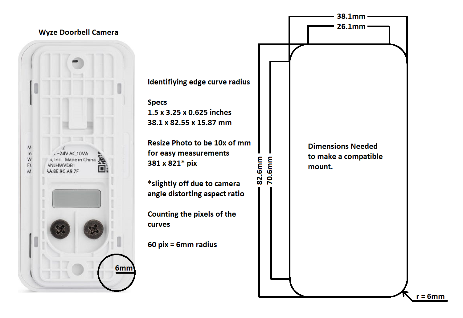
Making a mount for the Wyze Doorbell Camera
I need a slightly different mount than the default plate included with my smart doorbell. Something to conform to the molding around my door and mate with the doorbell itself. 3D printing will do the job well. To make a 3D print that perfectly mates with something requires specific measurements. Typically, you need the item in hand and you measure with a digital caliper and then gives those dimensions to your CAD drawing. The Wyze Doorbell Camera is a already a great product from a great company, but it doesn’t ship for 3 months. Time to do a little reverse engineering and create a configurable SCAD script. I can create…
-
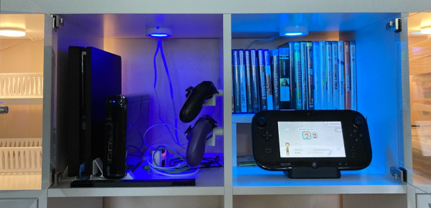
Game Cabinet Lighting with Neopixels
I put together some ikea cube shelving and wanted a place to keep my game consoles while also displaying them. I started with 3d printing some vertical stands for the PS4 and WiiU along with some controller hangers and riser shelves. I then added puck lights to the surrounding shelves, but wanted special lighting for the game shelves. Using some spare puck lights, neopixel rings, and a trinket I created some smart puck lighting that responds to which game system is powered. Power up the PS4 and the shelves are bathed in blue light. Power up the WiiU and the shelves turn cyan. Power both, and get both blue and…
-
Changing Win 10 Application Icons
In all previous revisions of windows, you could simply right click on any shortcut and change the icon as you please. Windows 10 still allows you to do this, but applications installed from the Windows Store are missing this ability. Unlike normal shortcuts, windows 10 applications do not have the option to change icons. Right click one and all you can do is visit App Settings or Rate and Review. You will not find Shortcut Properties and no way to Change Icon. You are the mercy of the developer to set the app icon (the worst feature on smartphones). If you drag a win10 store app, such as Calculator, to…
-
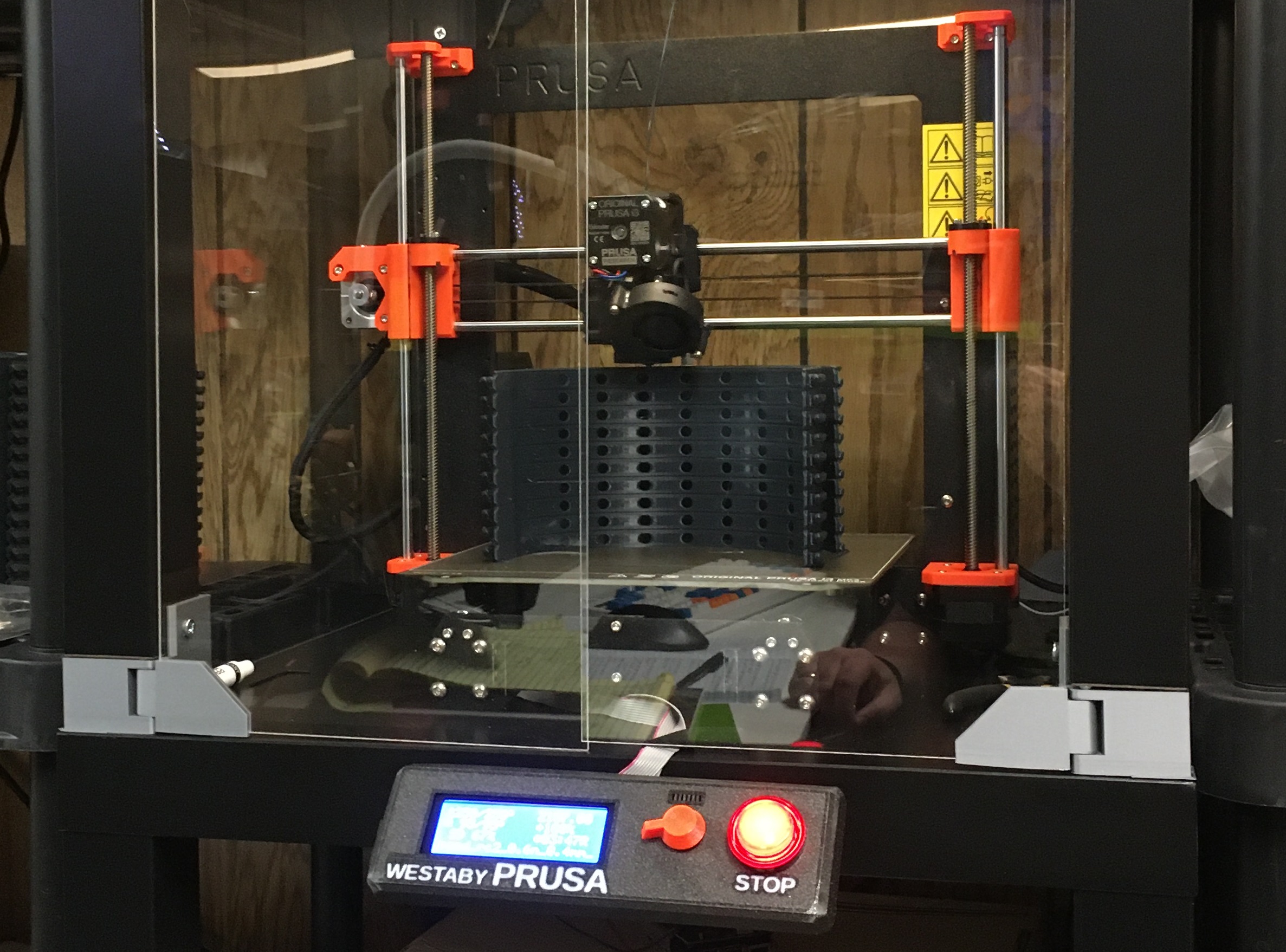
Prusa MK3S ~ Stop Button
This was a one day build. I leave my printer running unattended and I know that others in my home would have trouble finding the reset button or off switch if/when something went wrong. Solution, add a big friendly stop button. I have built several arcade machines over the years, so I had plenty of control panel buttons. This is a 46mm 12V red button. I pulled apart the switch and swapped the built in resistor to be 100 ohms, so I could run from 5V. Prusa’s 3D printers are open source. Even better, they design their 3D printed parts using openscad. My favorite 3D CAD program. https://github.com/prusa3d/Original-Prusa-i3/tree/MK3S I grabbed…
-
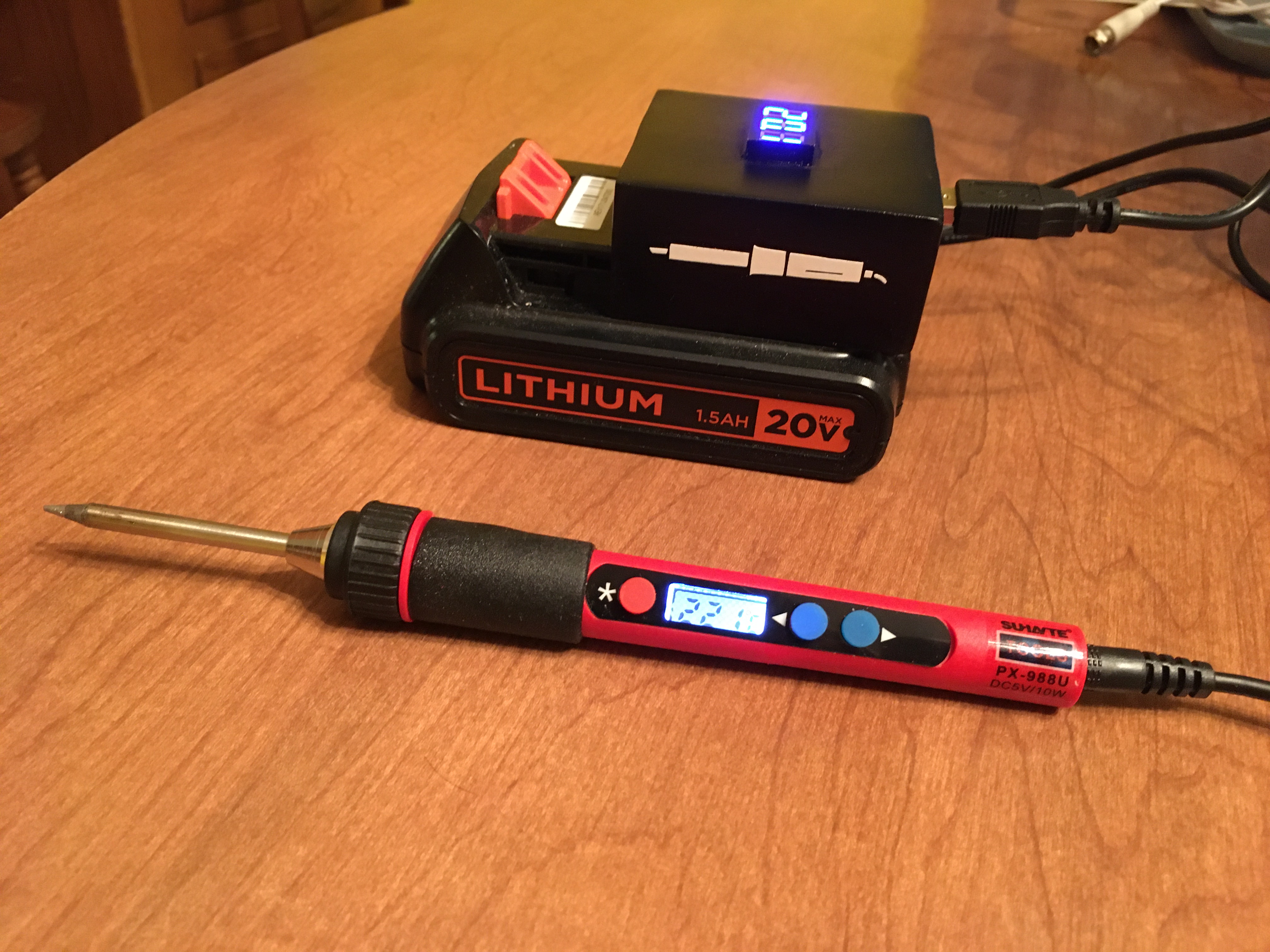
Portable Solder Iron
On a whim, I purchased a $20 USB Solder Iron from Aliexpress to play with. After playing with it using an old phone charger, I saw a video on Adam Savage’s Tested channel and got inspired. Drill Batteries as the power source. What a great idea! I have lots of those and always keep a few charged up and ready for projects. However, finding a drill battery adapter for my Black and Decker 20V set was a challenge. It’s all discontinued. Black and Decker only sell new bluetooth batteries with USB ports built in. No adapters to be found. Searching for a solution, I found forum posts saying that black…
-
Wifi sucks and How to fix
Do you experience periodic internet dropouts or wifi devices slow or not working sometimes, the only solution being to wait it out or unplug and replug in your router? There is a better way. This is a fix it and explanation guide for why your wifi internet sucks. I have a lot of CenturyLink specific advice, but the wifi fixes are for everyone. My story:When CenturyLink’s wifi router was in command of my network, I would have to power cycle on a weekly basis, sometimes multiple times a day. Even when the internet light was on, several of my devices wouldn’t connect. Later on, I traced the issue to a…
-
Xbox One is a Failure, History of a Generation
It is 2018 and the Xbox One came out in 2013. Let’s reminisce. Back in the days of Xbox 360, looking forward to the next generations that seemed impossible for Microsoft to do wrong. The Xbox 360 had a massive lead. If you were an online gamer. Shooter, racer, whatever… You owned an Xbox 360. You may have even owned multiple Xbox 360s over the years. I lost count of how many I went through. The Xbox 360 had issues, sure, but that didn’t stop Microsoft from racking up a huge sales in USA. Nearly double the competing PS3. Quick History Lesson The early Xbox 360s had a tendency to…
-
Fake Window – Smart Room Light
This is an overview of my Smart LED Window, based on an instructable by dannyk6. I took mine a step further by adding Alexa voice control and IFTTT day/night schedule. The wife picked the valance fabric. After remodeling my basement, I was left with the main area that had no natural light source. I didn’t like the idea of adding more nightlights, I could do better. I really wanted a flat panel tv linked to an outdoor camera, so you could see the front porch in real time. I could have the tv mounted vertically and dressed up to look like an actual window. I tried to design this Camera…