LTAR Display

I love the lazer tag augmented reality (LTAR) tagger. When playing unhosted grab and go game types, your choices are between the LTAR and the LTX taggers for 25 health gametypes. The LTAR handles much nicer in my opinion, but without an iphone the LTAR lacks any indicator of health / shields remaining during gameplay.
To solve this, I wrote some software to put on my existing ammo counter circuit. The software allows my circuit to sync with the LTAR during gameplay, or at least anticipate an accurate count of health and shields remaining. This post will serve as a guide of assembling the ammo counter circuit, modifying the LTAR, and installing the circuit. Usage and troubleshooting is at the bottom.
The LTAR Display kit is available in the store.
Updated (Jan 7th, 2014): Added hosted gametypes.
Assembly and Testing of the Circuit
The circuit kit comes unassembled. All parts in the kit are through-hole type and can be soldered by hand. The pin arrangements are tight, and you may need to use desolder braid to correct any mistakes while soldering.
Tools and Materials Required
- Solder Iron
- Stranded Wire
- Desolder Braid
Circuit Assembly Instructions
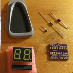
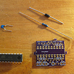
1. Make sure you have all the parts. Your kit included:
|
 |
| 2. Trim the PCB. The circuit board may have flanges on the edges, these are easily snapped off with a pliers. | 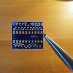 |
| 3. Examine the circuit board and chip. Find the pin 1 indicators, this is a small indentation on the chip and a white half circle on the circuit board. Place the chip onto the circuit board and solder in place. | 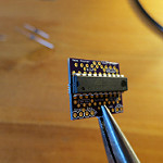 |
| 4. Depending on your circuit board revision, you may have extra spots that will be left blank. Follow instructions for your board revision. | |
Board revision 3.11: |
|
| 1. Place the capacitor and resistor as shown. Capacitor in the 0.1uF spot and Resistor in the left side (reset) 10kohm spot. | 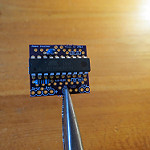 |
| 2. Solder in the resistor. | 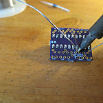 |
| 3. Trim the excess lead from the resistor. | 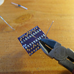 |
| 4. Solder in the capacitor. | 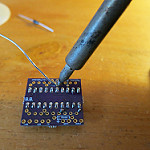 |
| 5. Trim the excess lead from the capacitor. | |
| 6. Flip the board and place the diode, take note of the line on one side for orientation. Do not solder yet, you will need to position below the display. | 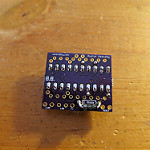 |
| 7. Examine the board to identify correct display orientation. Notice the periods in the 8.8. Place the display into the board following the indicated orientation, do not solder yet. | 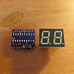 |
| 8. Use a pliers to bend the diode below the display, this will pull the diode out of the board slightly. | |
| 9. Now you may solder down the diode and display. | |
10. Lastly, add five 10 inch wires to the following locations on the bottom of the board (either use colored wires or label the wires for future reference). When soldering the wires, bend them upward. During install, clearance space will be tight at the bottom of the board.
|
 |
| 11. Your circuit is now assembled and ready for testing, proceed to the next step below. Note: You will have extra spots left blank on the 3.11 board revision. When you finish, you will have open spots for a top 100 ohm resistor and a right side (fire) 10kohm resistor. These are supposed to be empty. |
|
Board revision 4.01 |
|
| 1. Solder in the capacitor into the 0.1uF spot. | |
| 2. Solder in the resistor in the bottom left side 10kohm spot. | |
| 3. Solder in the resistor in the top right side in the 150 ohm spot.Note: This resistor determines the brightness of the display. A 150 ohm resistor makes the display a reasonable brightness. However, you may wish to swap in a lower value resistor to make the screen brighter. You may also short this spot with a wire for maximum brightness (not recommended). | |
| 4. Solder in the diode, take note of the line on one side for orientation. | |
| 5. Flip the board and identify the correct display orientation. Notice the periods in the 8.8. Place the display into the board following the indicated orientation. Solder in place. | |
6. Lastly, add five 10 inch wires to the following locations on the bottom of the board (either use colored wires or label the wires for future reference). When soldering the wires, bend them upward. During install, clearance space will be tight at the bottom of the board.
|
|
| 7. Your circuit is now assembled and ready for testing, proceed to the next step below. |
Circuit Testing
You now have an assembled circuit. Before powering up for the first time, take a moment and examine your work. Look for any solder bridges (shorts) and cleanup as needed. If you have a 2 or 3 AA battery pack, you may use it to power up the circuit. If you do not, you can use the LTAR’s battery pack. Wire the Batt Ground and Batt + wires from the circuit to three batteries only. DO NOT OVERPOWER. The circuit can only handle voltages up to 5.5volts. The LTAR is capable of voltages up to 9 volts.
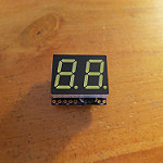
If all went to plan, your display should now be lit. Because the other wires are not connected, your display should also count down from 10 to 0 indicating a game has started.
Ensure all segments of the display are lighting through the countdown sequence. If any segments of the display do not light up, recheck the solder joints of each pin of the display. Then recheck the solder joints to the chip. If still unsuccessful, poke each joint with the solder iron and add more solder.
Modifying the LTAR
Congrats~! You have a working circuit and will now prepare the LTAR to install the display. Two dremel bits are recommended, the cutting wheel and the felt polishing wheel.
Tools and Materials Required
- Screw Driver
- Rotary Sander (dremel)
Instructions
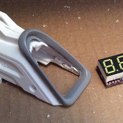
- If you have a bezel, you will notice that there is excess material. Cut off the extra plastic with a sharp knife or use a dremel tool. Polish the edges when done to give the bezel a smooth appearance.
- Remove the top sight attachment from the LTAR. This is the piece we will modify to hold the display.
- Hold the bezel against the sight and mark the inner and outer edges. This will be your guide for cutting.
- Remove the screws from the sight attachment and separate into halves. This will make cutting the internal structures easier.
- Cut out the inner edge markings. Do not cut out the outer area, this will be needed to glue the bezel to.
- Determine where you will place the display. It must be low enough to fit behind the wide section of the bezel and high enough to cram the wiring. The better you are at making the display flush with the bezel and overlay, the more crisp the numbers will appear behind the overlay*.
- In the area that will contain the display, cut a square area out. Use the outer edge markings.

- Continue adjusting until you are satisfied. At this point, you may want to use your dremel’s soft polishing wheel to knock down any rough edges.
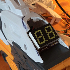
* This is a mistake I made in my initial prototype. In the pictures, you can see the display is slightly blurry and light leaks from the edges. This was caused by an approx 1cm gap between the bezel overlay and the display. The light reflects off the overlay and goes where light shouldn’t.
Installing the Display Circuit
At this point you should have an assembled circuit and a modified LTAR sight attachment. You are now ready to open the LTAR and wire the display into the LTAR’s main board.
Tools and Materials Required
- Screw Driver
- Solder Iron
- Hot Glue Gun or Epoxy
- Hot Air Gun or Hot Water
Instructions
- Remove the battery tray and open the LTAR. There are 11 screws on the main body, 2 screws in the shield arm, and 4 screws in the sight attachment.
- When removing the shield arm, be careful of the spring. Note it’s position before gently removing.
- When you first open the LTAR, be sure to grab the battery tray bolt. It is loose and easily lost.
- With the LTAR open, take a moment to examine the layout. There is no need to remove the fire / shield buttons, main board, forward lens assembly, or the top receiver dome. We will be soldering the display circuits wires to the top of the main board.
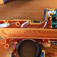
- You have two choices for running the wiring. You may use the existing square hole that currently houses the iphone headset cable or cut a new hole. In my prototype, I chose to relocate the iphone headset cable internal (in case I needed it later), see picture.
- Position the display circuit above the LTAR, you will need to leave approx 5 inches of wire slack between the LTAR shell and the circuit.
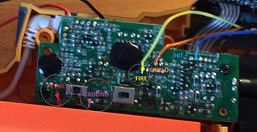
- Route the wires around and below the main board as needed to reach the positions pictured. Trim the excess wire lengths.
Notes: It is hard to tell in the picture, but there is a chip resisistor just above the fire signal location, be careful not to solder the fire wire there.
- If everything looks good, go ahead and insert the battery pack. No need to close the LTAR shell yet.
- You should immediately see the display light up, even if the LTAR is still off. This is correct operation.
- Flip the switch to turn on the LTAR, the display will flash for a moment.
- Press the shield button to test toggling gametypes.
- Press the fire button to begin a game.
- Use a second tagger to test receiving hits and the display reports health remaining.
- Pregame and postgame, the display will power down after 60 seconds of no button presses. You can re-awaken by turning the LTAR on/off.
- Once satisfied that the circuit is installed correctly, you may now reassemble the LTAR. If you are having trouble with the wiring, please email me a picture of your LTAR’s main board and display circuit wiring.
Note: The trickiest part is reinstalling the spring loaded shield button, you remember how it was positioned, right? - With the display wiring installed / routed and the LTAR re-assembled, you can now glue the display into the LTAR sight attachment and screw together. Should look something like the picture now.
Note: DO NOT glue the display circuit or sight attachment to the LTAR body. You will still need to access the to the inside of the sight / display to finish the install.
- Next up is the bezel. Position above the display and test the fit with the overlay. This is your last chance for any late adjustments. Remember, the overlay must be flush with the display to look best, any gap will lead to a cloudy display.
- Remove the overlay, and use hot glue to affix the bezel over the display. Be sparing with the glue as we will be covering it with stronger polymorph plastic next.
- You now have a nice bezel atop your display, but no overlay and there is an ugly gap between the plastic of the bezel and the plastic of the sight attachment. Breakout the polymorph plastic.Side rant: I really love polymorph plastic. Simplifies the the process of bondo and sanding and resin hardener and curing… all down to melting some beads and smushing them into place. If you mess up, just reheat and try again and again and again :D
- To melt the beads, I use a temperature controlled hot air gun set to 100C, the melting point of the beads is only 60C so I stop heating when the beads turn from white to clear. At 60C the beads are safe to handle and a bit sticky.
Note: Be careful here. The LTAR plastic is also made from thermoform plastic, meaning it will melt when it gets hot enough. 100C is not enough to melt the LTAR body, but your hot air gun may be more powerful. A non-temperature regulated hot air paint stripper for example gets up to 600C, which is plenty to melt EVERYTHING. You are better off using the hot water method. See youtube for some tutorials.
- Click the pictures for a closer look. Place the beads in a row, heat with hot air until the beads change color to clear. Then push into the gap. Repeat until the gap is filled all the way around the outside of the bezel.
- Continue reheating as needed to push the edges into a nice clean and straight shape.
- You may use the dremel felt polishing wheel here to smooth the plastic further, removing fingerprints ;) Be careful and polish in short strokes with time between for the plastic to cool. The friction of the polish wheel is enough to reheat the polymorph to become pliable.
- Ok, FINALLY, it is time to install the overlay into the bezel. Use hot glue on the top and bottom. Remove the sight attachment / display from the LTAR body to add glue between the overlay and the bezel walls.
- Cleanup time. More polish, some painting. Not shown in pictures.


Usage
Using the display with your LTAR is straightforward. A quick demo can be seen in the video below.
Unhosted Games:
- Turn tagger off and on, this will wake the display
- Press shield button to switch between 10 and 25 health gametypes.
- Press trigger to start game, 10 second countdown begins
- Display will show remaining health / shields during game.
Hosted Games
TBD
Custom Number Entry
TBD
Troubleshooting
Here are some fixes to common issues with the LTAR display.
I turned my gun off mid-game and now the display won’t turn off.
Turn the LTAR on and off, this will reset the display and allow it to power off after 60 seconds.
I tapped the shield button, and now the display is out of sync with the gun.
This can be caused by not holding the shield button long enough. When using an LTAR with a display installed, give the shield button a good solid press (1/2 second is plenty) so that both the LTAR and the Display can see the button press. Brief button presses can be missed by one or both circuits due to scheduling / debouncing routines. Recommend experimenting with different button press styles to ensure you can manage yourself in the field.
I turned off my shield and was still holding down the shield button when I was shot, now the display is out of sync with the gun.
Yeah, don’t do that.